PC Based Measuring Devices · since 1996

Measuring instruments for your PC

USB oscilloscopes, arbitrary waveform generators, logic analyzers and accessories – designed and manufactured in Žilina, Slovakia.

About us

ETC s.r.o. is focused on design and production of electronic devices mostly in the field of measuring, testing, controlling and computers. We also design software and firmware. The company was founded on 1st January, 1996.

The activities of the ETC company can be divided into two groups:

  1. development, manufacturing and sale of PC based measuring devices of our own design
  2. design, development and, optionally, production of devices according to customers' specifications. The devices in concern are especially control computers, communication computers, special adds-ons, OEM and embedded devices.

The company cooperates closely with The University of Zilina. It uses advanced technologies and parts in designing and manufacturing process. Digital logic is mostly implemented by the FPGAs and CPLDs. The Surface Mount Technology (SMT) is widely utilized in the production process.

Services

  • Consultancy on formulation of the most suitable solution
  • Preparation of a project and detailed task specification
  • Development of software and hardware (including firmware)
  • Development and production of hardware and software necessary for serial production
  • Creation of blueprints for production and writing user's guide
  • Production of prototypes and testing series
  • Mass production

Markets

Products of ETC s.r.o. are exported worldwide. ETC s.r.o. has distributors in several countries that supply their regions regularly. All ETC products are CE certified.

Our dealers

DownloadsSoftware, drivers and manuals FAQAnswers from technical support Price listCatalogue numbers and prices ContactSales department and technical support

Products

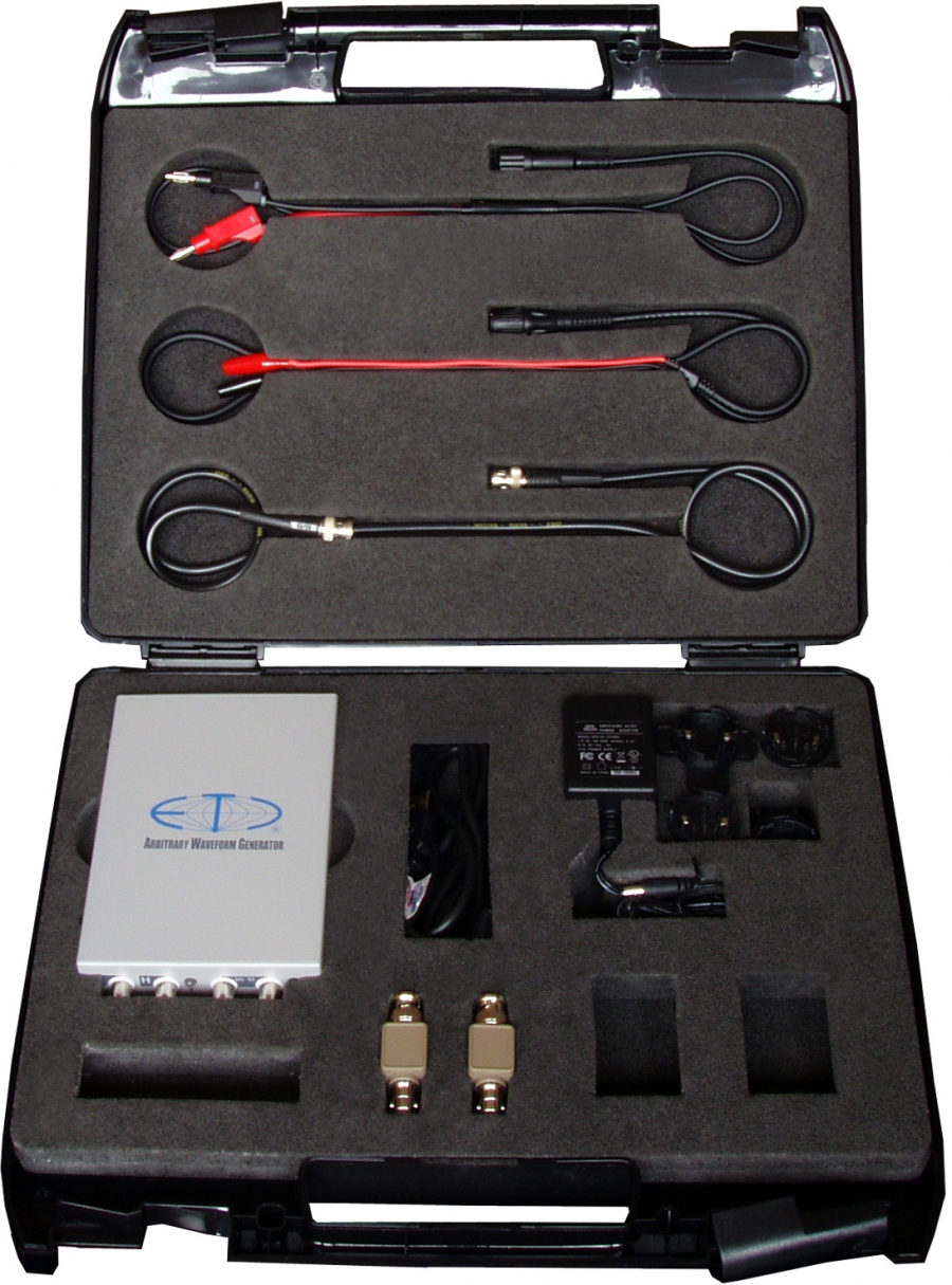
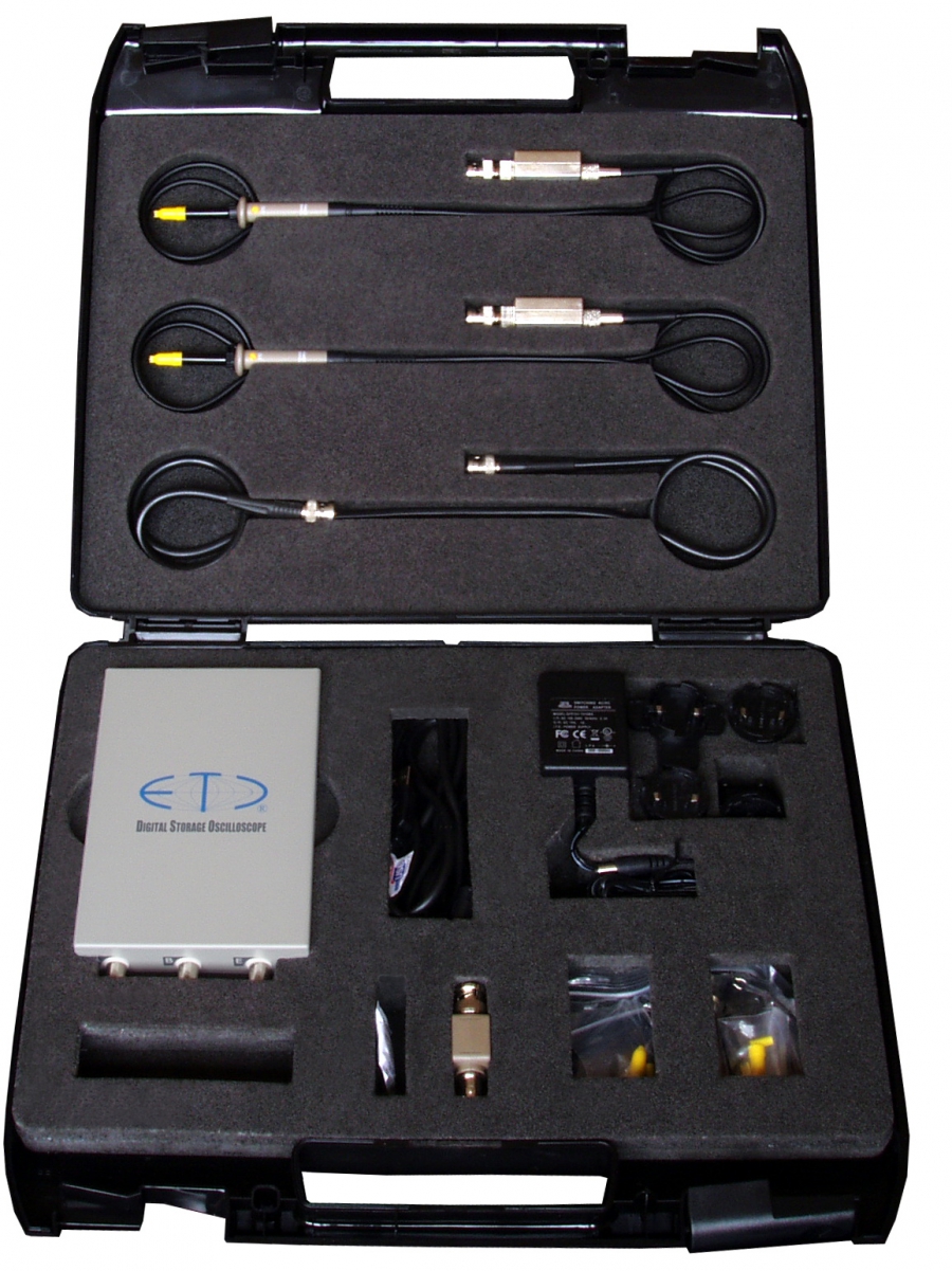
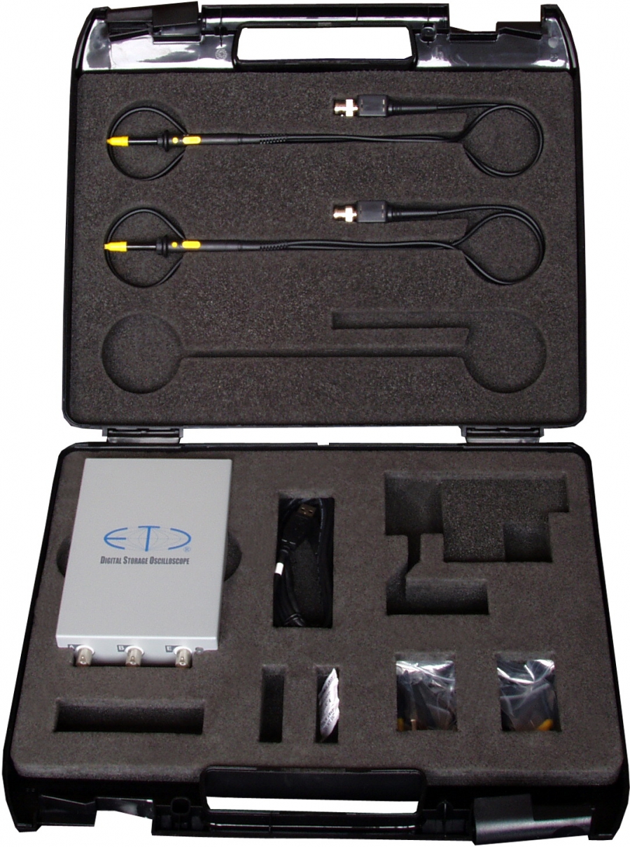
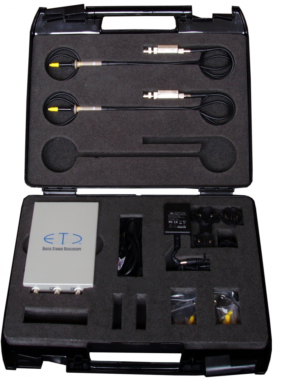
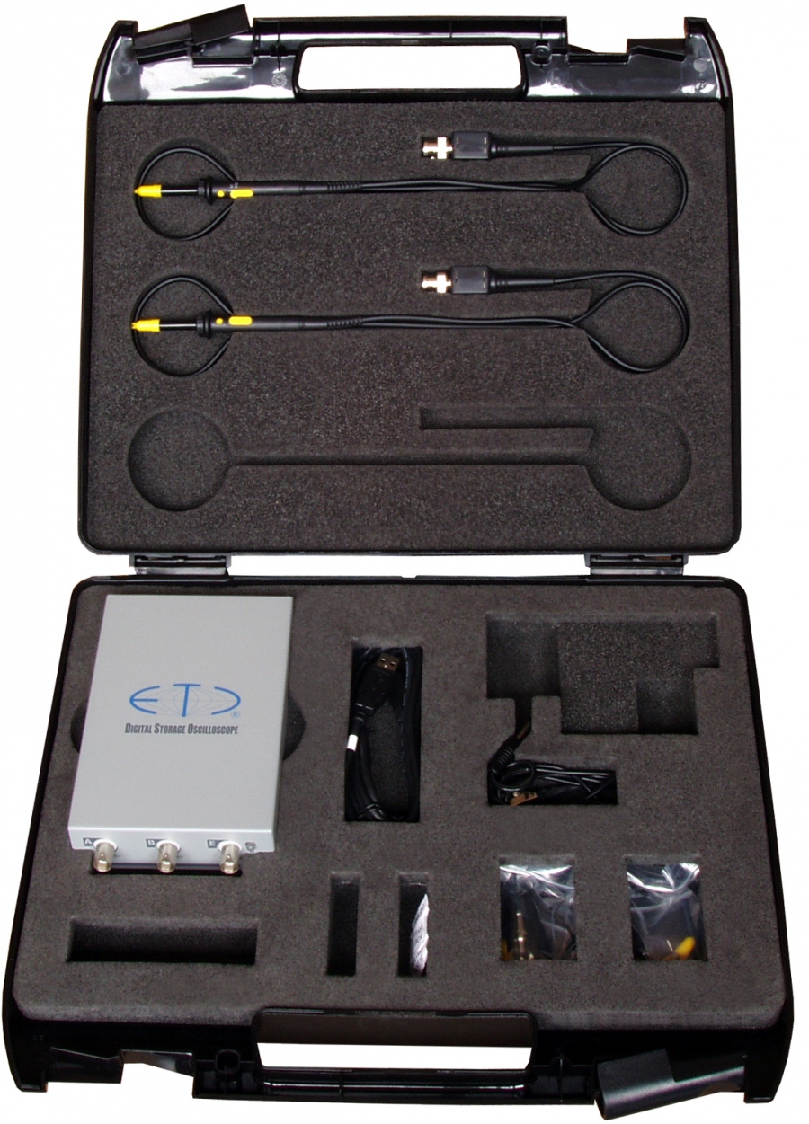
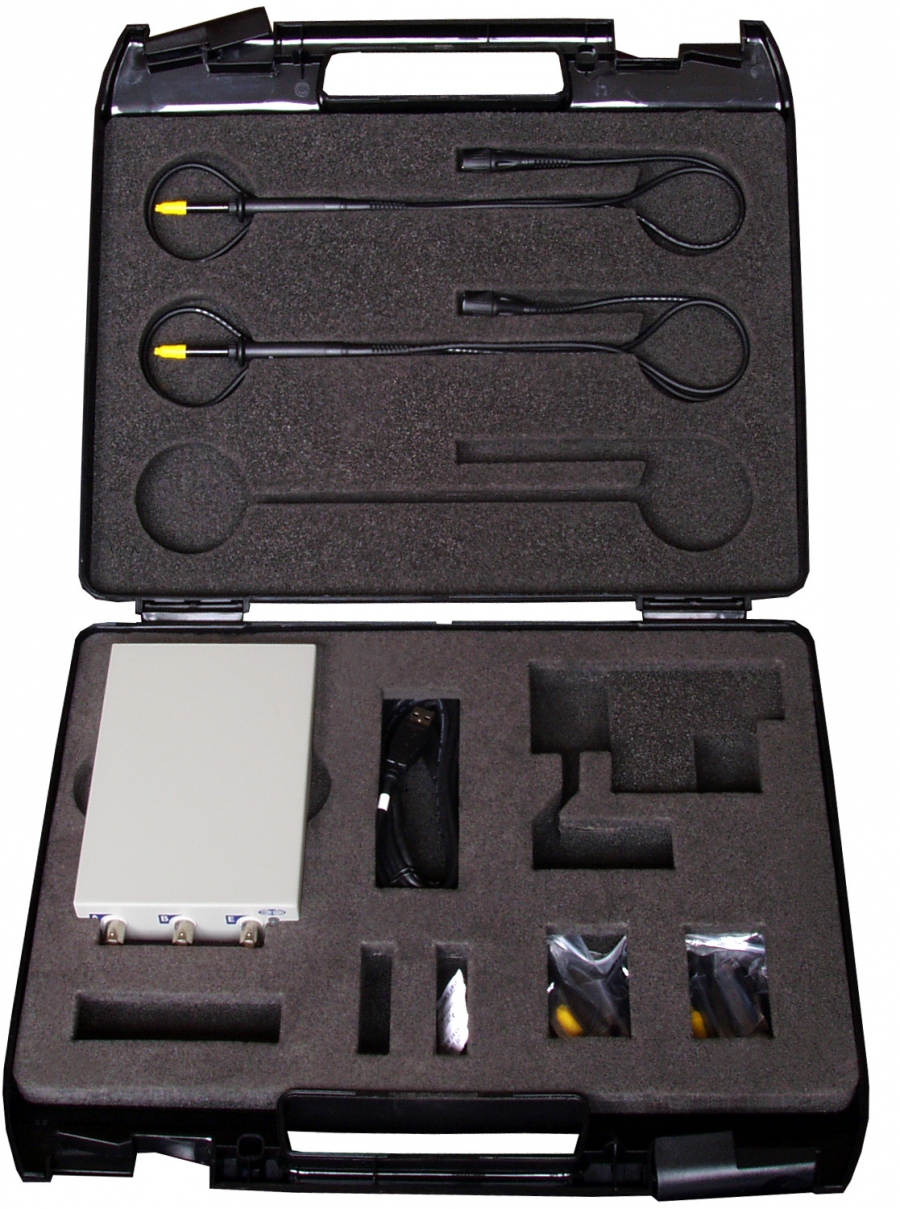
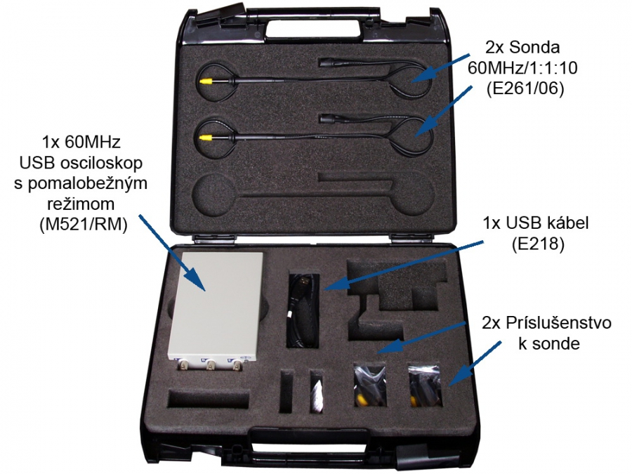
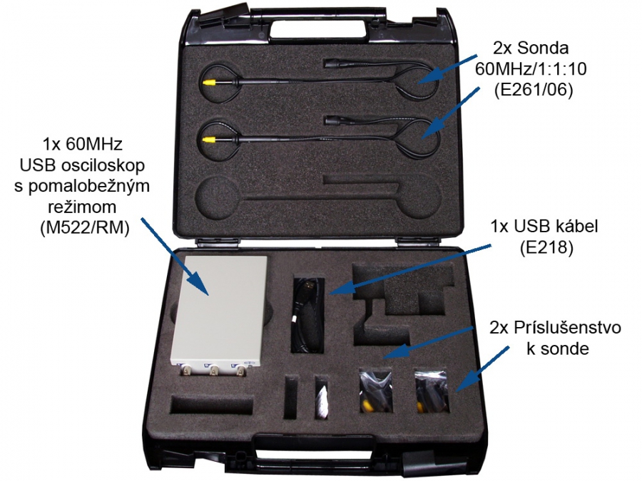
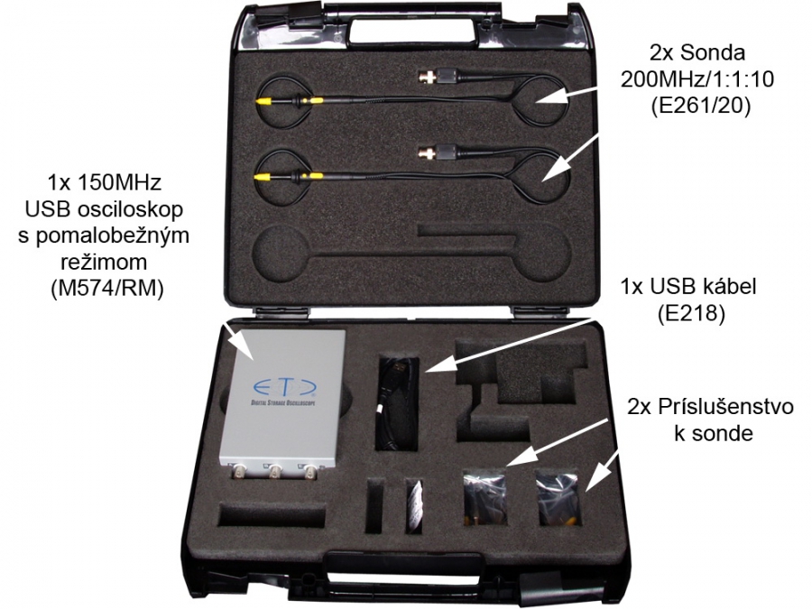
Kits contain the instrument, software and the accessories typical for the application. The kit is packed in a tough plastic carry case.

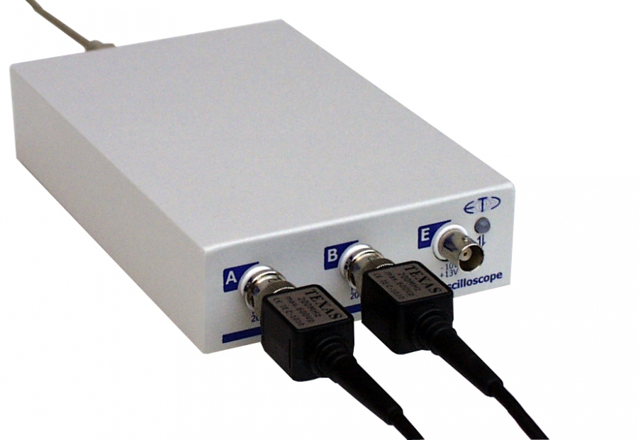
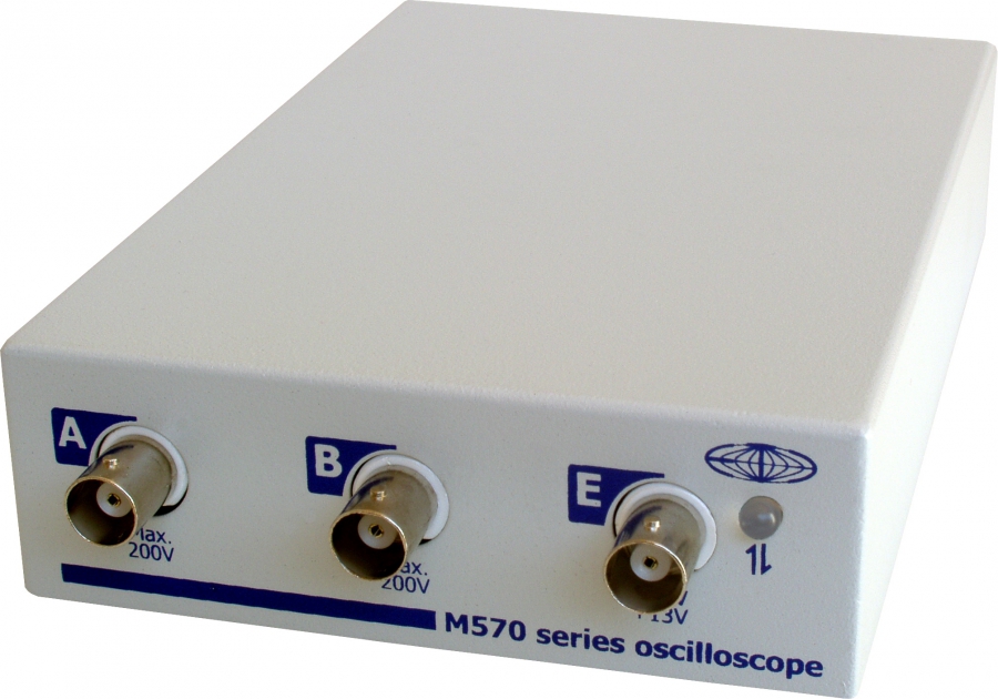
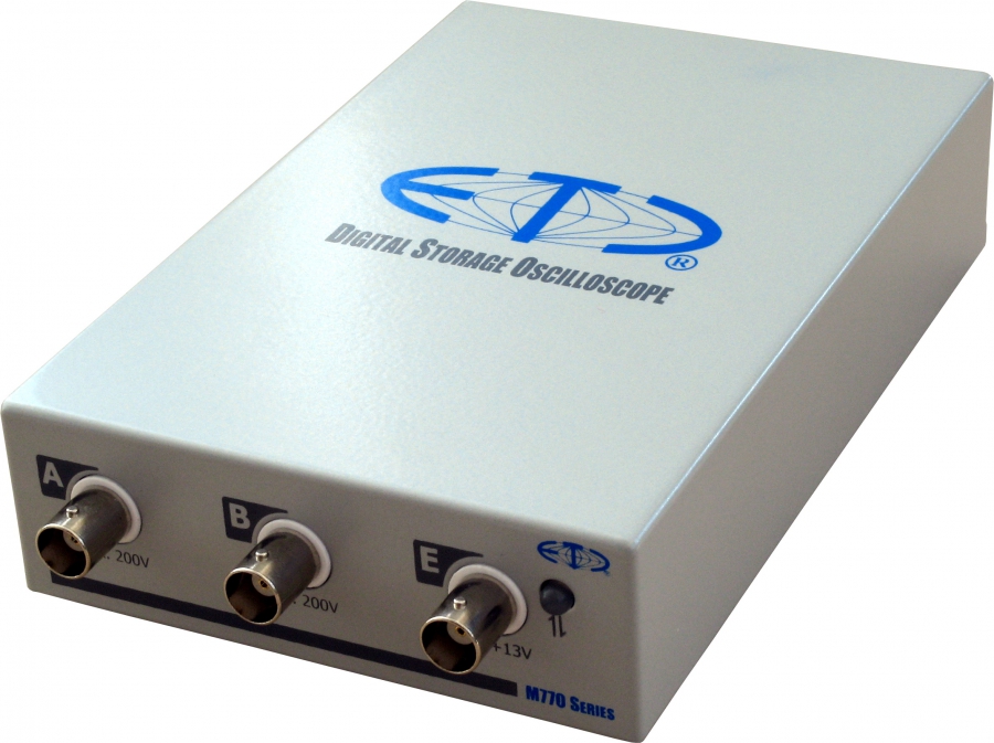
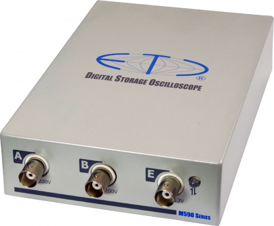
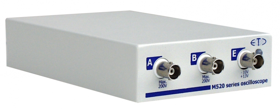
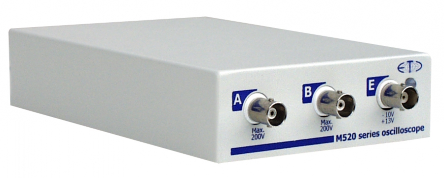
USB oscilloscopes connect to the computer via USB and use the computer's screen to display the measured waveforms.

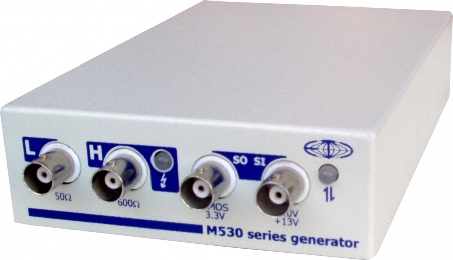
Arbitrary waveform generators that connect to the computer.

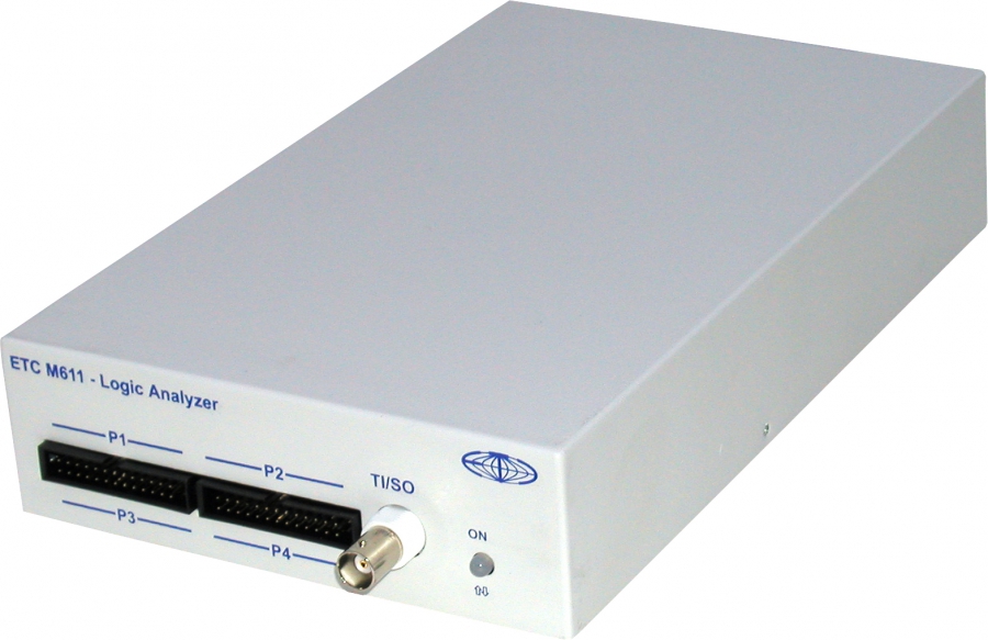
Logic analyzers that connect to the computer.

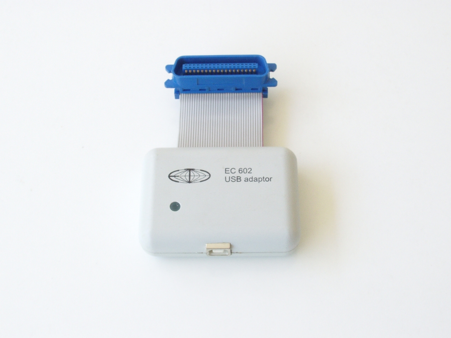
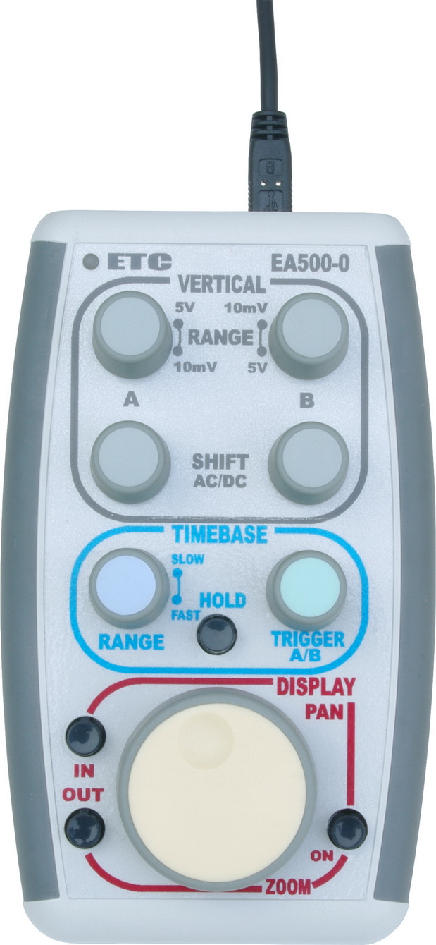
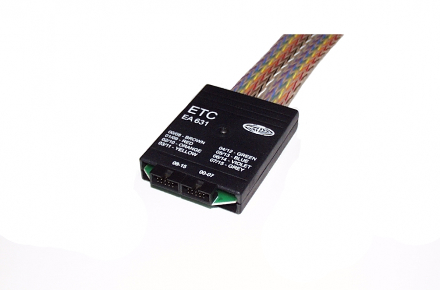
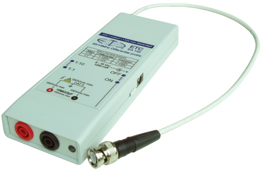
Auxiliary equipment provides various additional functions.

We offer several versions of a modern measurement laboratory for technical subjects such as Electrical measurement, Electronics, Electrical engineering, Automotive diagnostics, Physics etc. The laboratory is built around USB oscilloscopes …

ET 091 School work module

Supports USB 2.0 and USB 1.1 No separate power supply needed Simple circuits can be built without soldering Can be used stand-alone …

Sample study materials

Type C laboratories are supported by study materials. They are supplied in digital form, both as PDF files and as editable DOC …

Laboratory set A524

Laboratory A524 contains Type number Description Quantity M524/RM Digital oscilloscope with roll mode 5 E261/20 Oscilloscope probe …

Laboratory set A526

Laboratory A526 contains Type number Description Quantity M526/RM Digital oscilloscope with roll mode 5 E261/20 Oscilloscope …

Laboratory set A574

Laboratory A574 contains Type number Description Quantity M574/RM Digital oscilloscope with roll mode 5 E261/20 Oscilloscope …

Laboratory set AC524

Laboratory AC524 contains Type number Description Quantity M524/RM Digital oscilloscope with roll mode 5 E261/20 Oscilloscope …

Laboratory set AC526

Laboratory AC526 contains Type number Description Quantity M526/RM Digital oscilloscope with roll mode 5 E261/20 Oscilloscope …

Laboratory set AC574

Laboratory AC574 contains Type number Description Quantity M574/RM Digital oscilloscope with roll mode 5 E261/20 Oscilloscope …

Laboratory set B524

Laboratory B524 contains Type number Description Quantity M524/RM Digital oscilloscope with roll mode 5 E261/20 Oscilloscope …

Laboratory set B526

Laboratory B526 contains Type number Description Quantity M526/RM Digital oscilloscope with roll mode 5 E261/20 Oscilloscope probe …

Laboratory set B574

Laboratory B574 contains Type number Description Quantity M574/RM Digital oscilloscope with roll mode 5 E261/20 Oscilloscope …

Laboratory set BC524

Laboratory BC524 contains Type number Description Quantity M524/RM Digital oscilloscope with roll mode 5 E261/20 Oscilloscope …

Laboratory set BC526

Laboratory BC526 contains Type number Description Quantity M526/RM Digital oscilloscope with roll mode 5 E261/20 Oscilloscope …

Laboratory set BC574

Laboratory BC574 contains Type number Description Quantity M574/RM Digital oscilloscope with roll mode 5 E261/20 Oscilloscope …

Laboratory set C524

Laboratory C524 contains Type number Description Quantity M524/RM Digital oscilloscope with roll mode 5 E261/20 Oscilloscope …

Laboratory set C526

Laboratory C526 contains Type number Description Quantity M526/RM Digital oscilloscope with roll mode 5 E261/20 Oscilloscope …

Laboratory set C574

Laboratory C574 contains Type number Description Quantity M574/RM Digital oscilloscope with roll mode 5 E261/20 Oscilloscope …

Laboratory set CC524

Laboratory CC524 contains Type number Description Quantity M524/RM Digital oscilloscope with roll mode 5 E261/20 Oscilloscope …

Laboratory set CC526

Laboratory CC526 contains Type number Description Quantity M526/RM Digital oscilloscope with roll mode 5 E261/20 Oscilloscope …

Laboratory set CC574

Laboratory CC574 contains Type number Description Quantity M574/RM Digital oscilloscope with roll mode 5 E261/20 Oscilloscope …

Kits

Kits contain the instrument, software and the accessories typical for the application. The kit is packed in a tough plastic carry case.

Wide bandwidth oscilloscopes

Oscilloscopes with a bandwidth over 300MHz and a real-time sampling rate over 500MS/s.

Arbitrary waveform generators

Arbitrary waveform generators that connect to the computer.

Terminators and attenuators

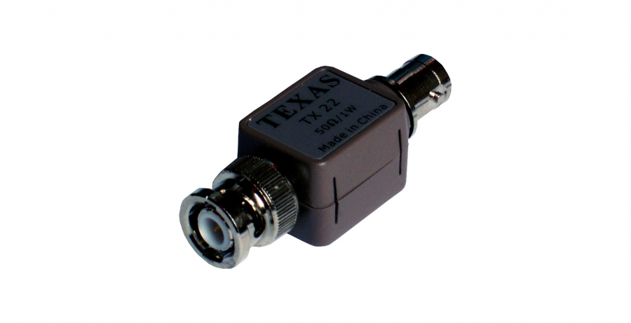
50 Ohm terminators and attenuators.

School laboratories


LaboratoryWe offer several versions of a modern measurement laboratory for technical subjects such as Electrical measurement, Electronics, Electrical engineering, Automotive diagnostics, Physics etc. The laboratory is built around USB oscilloscopes whose bandwidth and software are suitable for professional work as well. Besides the digital oscilloscope function, they also work as a spectrum analyzer and a two-channel data recorder.

On exceptionally favourable terms we offer three types of laboratories. For each type you can choose the oscilloscopes the laboratory will be equipped with, and whether computers will be part of the delivery. If computers are supplied, their type will be specified according to the customer's requirements.

Laboratory type A consists of five digital oscilloscopes, each with two probes, and the accessories needed to operate them. We offer six variants: A524, A526, A574, AC524, AC526 and AC574.

Laboratory type B consists of five digital oscilloscopes, each with two probes, and the accessories needed to operate them, plus a 350 MHz digital USB oscilloscope for demanding measurements, usually for the teacher. We offer the following variants: B524, B526, B574, BC524, BC526 and BC574.

Laboratory type C consists of five digital oscilloscopes, each with two probes, and the accessories needed to operate them, plus five ET091 school modules connected in a local network. The modules are centrally controlled by the teacher and generate various waveforms and events for teaching. Laboratory type C is supported by a set of solved laboratory exercises with oscilloscope settings and programs that control the school module. Six variants are available: C524, C526, C574, CC524, CC526 and CC574.

Installation and training at the customer's site can also be ordered with the laboratories.

ET 091 School work module

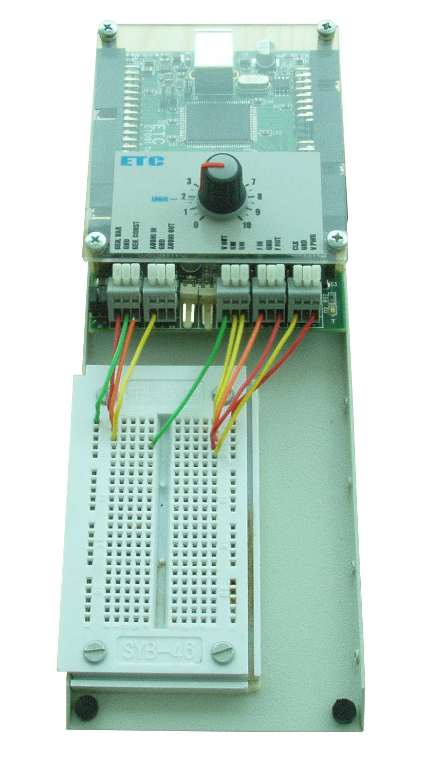
Supports USB 2.0 and USB 1.1 No separate power supply needed Simple circuits can be built without soldering Can be used stand-alone …

Sample study materials

Type C laboratories are supported by study materials. They are supplied in digital form, both as PDF files and as editable DOC …

Laboratory set A524

Laboratory A524 contains Type number Description Quantity M524/RM Digital oscilloscope with roll mode 5 E261/20 Oscilloscope probe …

Laboratory set A526

Laboratory A526 contains Type number Description Quantity M526/RM Digital oscilloscope with roll mode 5 E261/20 Oscilloscope …

Laboratory set A574

Laboratory A574 contains Type number Description Quantity M574/RM Digital oscilloscope with roll mode 5 E261/20 Oscilloscope …

Laboratory set AC524

Laboratory AC524 contains Type number Description Quantity M524/RM Digital oscilloscope with roll mode 5 E261/20 Oscilloscope …

Laboratory set AC526

Laboratory AC526 contains Type number Description Quantity M526/RM Digital oscilloscope with roll mode 5 E261/20 Oscilloscope …

Laboratory set AC574

Laboratory AC574 contains Type number Description Quantity M574/RM Digital oscilloscope with roll mode 5 E261/20 Oscilloscope …

Laboratory set B524

Laboratory B524 contains Type number Description Quantity M524/RM Digital oscilloscope with roll mode 5 E261/20 Oscilloscope …

Laboratory set B526

Laboratory B526 contains Type number Description Quantity M526/RM Digital oscilloscope with roll mode 5 E261/20 Oscilloscope probe …

Laboratory set B574

Laboratory B574 contains Type number Description Quantity M574/RM Digital oscilloscope with roll mode 5 E261/20 Oscilloscope …

Laboratory set BC524

Laboratory BC524 contains Type number Description Quantity M524/RM Digital oscilloscope with roll mode 5 E261/20 Oscilloscope …

Laboratory set BC526

Laboratory BC526 contains Type number Description Quantity M526/RM Digital oscilloscope with roll mode 5 E261/20 Oscilloscope …

Laboratory set BC574

Laboratory BC574 contains Type number Description Quantity M574/RM Digital oscilloscope with roll mode 5 E261/20 Oscilloscope …

Laboratory set C524

Laboratory C524 contains Type number Description Quantity M524/RM Digital oscilloscope with roll mode 5 E261/20 Oscilloscope …

Laboratory set C526

Laboratory C526 contains Type number Description Quantity M526/RM Digital oscilloscope with roll mode 5 E261/20 Oscilloscope …

Laboratory set C574

Laboratory C574 contains Type number Description Quantity M574/RM Digital oscilloscope with roll mode 5 E261/20 Oscilloscope …

Laboratory set CC524

Laboratory CC524 contains Type number Description Quantity M524/RM Digital oscilloscope with roll mode 5 E261/20 Oscilloscope …

Laboratory set CC526

Laboratory CC526 contains Type number Description Quantity M526/RM Digital oscilloscope with roll mode 5 E261/20 Oscilloscope …

Laboratory set CC574

Laboratory CC574 contains Type number Description Quantity M574/RM Digital oscilloscope with roll mode 5 E261/20 Oscilloscope …

Universal oscilloscope kit

Universal oscilloscope kit

The universal kit is designed to meet the most measuring requirements. It allows you to measure in wide range of systems and (thanks to the isolation) it reduces grounding errors, which could affect measurement results.

The accessories in this kit allow you to perform most measurements in lab and several special measurements in power systems.

This kit is suitable to universal use of the oscilloscope.

Oscilloscope

Unique construction of the M774 oscilloscope provides pair of the isolated inputs. Isolation introduces increased security when measuring the voltage beyond safe level, makes measurement much more resistant to noise caused by grounding to multiple points.

This makes the device perfect for the measurement on the complex systems, where the probability of the multiple grounding is quite high (such as communication hubs). The M774 is ideal for measurements on the power systems, because the isolation together with possibility of safety grounding greatly decreases risk of the electric shock.

The 1MS memory per channel enables you to perform detail analysis of the fast, long processes (such as digital communication).

Device uses metal casing, which withstand rough manipulation and is fully recyclable.

The M774 offers precise electronic engineering (as is usual in all ETC devices) and automated calibration processes during manufacturing. Each kit contains the traceable calibration certificate. The inputs withstand +-200V, which is quite rare in this category.

The used memory size is configurable. This allows you to easily switch between high update rates (short memory) and the high data amounts (large memory). Since the M774 device uses USB 2.0 for communication (with automatic fallback to USB 1.1), the device provides you with high refresh rates comparable to the stand-alone devices.

Software

The basic package contains complex, yet easy to use, oscilloscope software (Scope). Scope allows you to easily control oscilloscope, use advanced functions (such as FFT, persistent display mode, mask testing) or export the data. The spectrum analyzer software is the part of the basic package as well.

The roll mode (each kit contains the license for the device), allows you to acquire the data as fast as 2.5MS/s and store them directly to the hard drive. You can use either viewer to analyze the data or export tools to analyze data in third party applications.

Support

The ETC appreciates your decision to purchase ETC device, so we offer you the support for unlimited time. Feel free to ask our technicians for help with the measuring task you are currently working on.

The software is available on our website free of charge. Once we add new feature to the basic package, you will be able to download it for a free.

Packaging

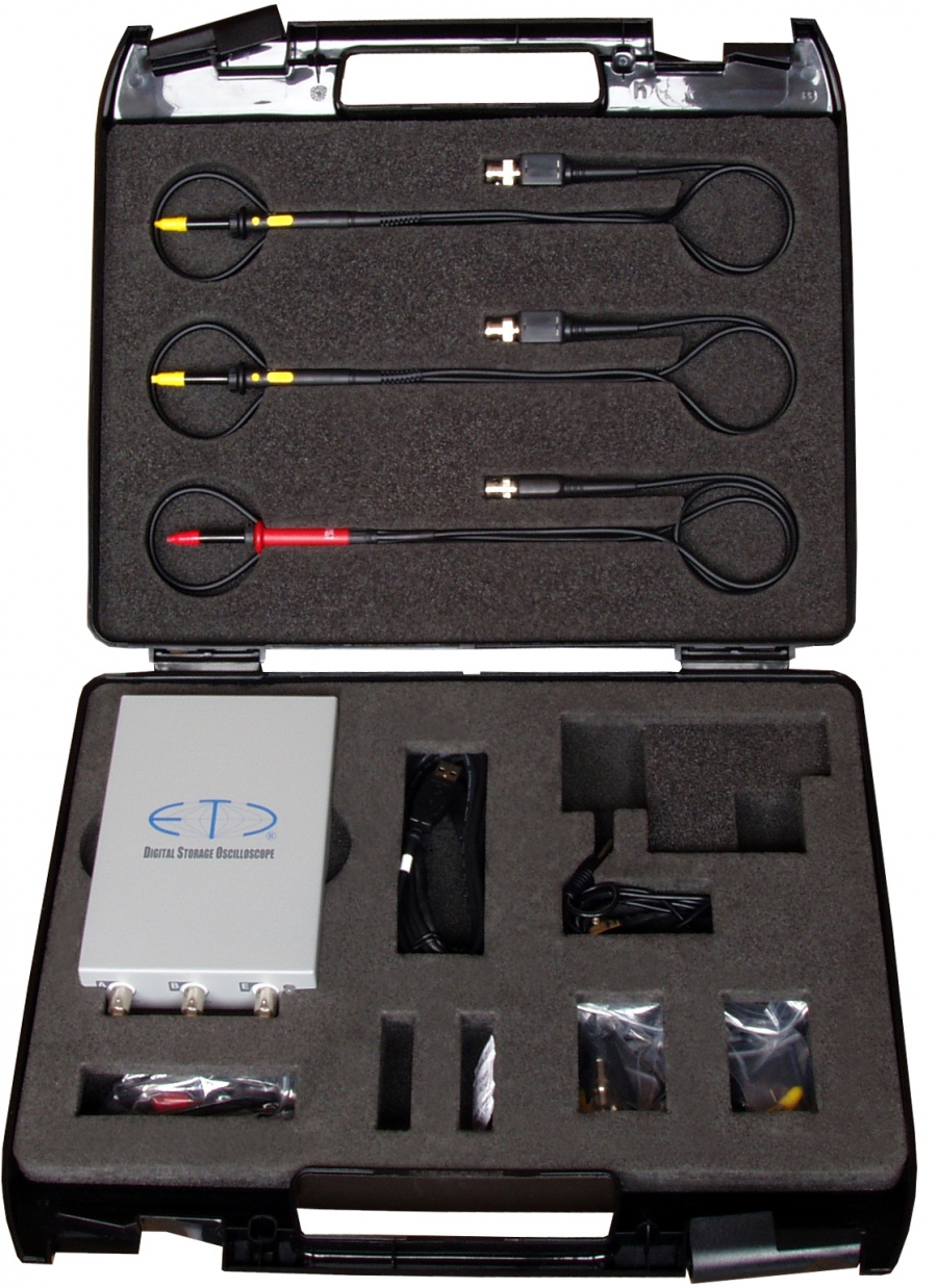
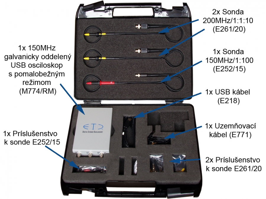
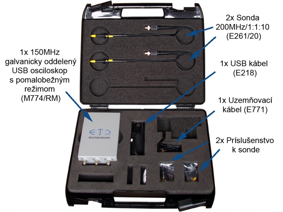
The universal kit is stored in the tough carry case, which protects the device and accessories even in harsh conditions and manipulation. Each component has the place in the foam specifically designed for it. This provides you with the comfort of easy packing and unpacking and protects the components from falling out in non-standard positions of the case.

The universal kit contents

The universal kit contents

Cat. number
Description
M774/RM 1x 150 MHz isolated digital storage oscilloscope with roll mode
E218 1x USB 2.0/1,8m cable
E252/15 1x Oscilloscope probe 150 MHz/1:100, 1,2m
E261/20 2x Switchable oscilloscope probe 200 MHz/1:1:10, 1,2m
E771 1x Safety grounding cable
1x CD with software and user´s guide
1x Installation leaflet
1x Warning leaflet
1x Calibration certificate
1x Declaration of conformity
M774
M774

M774 150MHz isolated oscilloscope

  • Compatible with USB 2.0 and USB 1.1
  • Inputs galvanically isolated from the computer
  • Two channels with 150MHz bandwidth
  • Sensitivity: 10mV/div to 5V/div in 1-2-5 steps
  • Maximum real-time sampling rate 100MS/s
  • Maximum equivalent sampling rate 10GS/s
  • Large internal memory: 1MS per channel
  • Software for Windows 98SE, Windows ME, Windows 2000, Windows XP, Windows Vista, Windows 7, Windows 8 and Windows 10 (1903)

The M774 digital storage oscilloscope is a member of the ETC Measuring Lab 3 (EML3) family.

The M774 is a two-channel oscilloscope connected via USB 2.0 or USB 1.1, with the computer circuits galvanically isolated from the measuring inputs up to 500V. Easy installation and connection to the computer make the M774 well suited for mobile use. The device is connected to the computer with a standard USB cable and is powered from it. With a maximum power consumption of 2.35W it works well with a battery-powered notebook.

The inputs use BNC connectors and are compatible with standard probes (with a minimum compensation range of 30pF). The internal memory (1M per channel) is used as a fast buffer for the measured waveforms.

The software is included in the M774 package. The latest version is available free of charge on our website. All standard functions of modern digital oscilloscopes (pause, delayed acquisition, zoom etc.) and many more (saving/loading waveforms for later use, export to the clipboard, printing a measurement together with the oscilloscope settings) are available.

The high transfer rate allows frequent screen updates (giving the feel of an analog oscilloscope).

Four acquisition modes are available (AUTO, NORMAL, SINGLE, MANUAL). Triggering is controlled by a two-level trigger system with a digital pulse filter and an occurrence counter on each level. Channel A, channel B and the external input can be selected as the trigger source. The trigger level of channels A and B can be set anywhere within the oscilloscope screen. The threshold of the external input is approximately 1.5V and is TTL and CMOS compatible. This sophisticated system allows synchronization with complex waveforms (e.g. selecting a line of a video signal).

In 1:1 zoom mode the time base can be set from 5ns/div to 100ms/div in 1-2-5 steps. Using other zoom modes, the time base can be set from 625ps/div to 204.8s/div.

The M774 package includes a printed installation guide and a detailed user's guide on CD. Context help is integrated into the software.

The software runs under Windows 98SE, Windows ME, Windows 2000, Windows XP, Windows Vista, Windows 7, Windows 8 and Windows 10 (1903). The size of the oscilloscope screen adapts to the monitor resolution (minimum 800x600).

Two optional software packages are available: the M770 Development kit, which allows you to create your own applications using the M770 devices, and the M770 Roll mode, which turns the oscilloscope into a data recorder.

M774 Performance Characteristics

Vertical deflection system

No of divisions 8
No of pixels per division 32
Deflection factor range 10mV/div to 5V/div in 1-2-5 sequence
Accuracy +- 2% of current value + 1 pixel
Resolution 8 bits (0,39%)
Frequency response (-3dB) DC: 0-150 MHz, AC: 1.2 Hz-150 MHz
Step response rise time max. 2.4 ns
Channel isolation min. –60 dB
Resistance 1 MOhm +5 %, -2 %
Input resistance inaccuracy adjustment Digital for absolute accuracy +- 2% of current voltage + 1 pixel
Capacitance 28 pF +- 2pF
Zero setting accuracy +- 2% of the screen
Maximum input voltage +- 200V at 100 kHz or less

Triggering

System type Dual level
Trigger source for primary level selectable Channel A, Channel B or external trigger input
Trigger source for secondary level selectable Channel A, Channel B or external trigger input
Threshold setting Channel A and Channel B on the whole display range. External fixed on about 1.5V
Slope selection Leading or trailing edge independently on each source
Minimum trigger pulse period 5 ns
Minimum trigger pulse length 2.5 ns
Maximum voltage on external trigger input –10V to +13V at 20 kHz or less
Adjustments Digital filter with ability of setting the valid pulse length up to 131072*Ts for each level and counter of valid triggering events settable from 1 to 32768 for each level. HOLD-OFF settable up to 1048576*Ts with selectable AUTO mode, to sample proper amount of data before trigger. (Ts – actual real time sampling period)

Data acquisition system

No of divisions 10
No of pixels per division 50
Mode of operation Sampling before and after trigger with continual selection of the trigger position
Record length settable from 1024 to 1048576 (1M) samples for each channel
Time base range in 1:1 mode 5 ns/d to 100 ms/d in 1-2-5 sequence
Time base range using different ZOOM modes 625 ps/d to 204.8 s/d
Time base accuracy 0.01 % to 100ns/d, 0.5 % for 50ns/d to 5 ns/d
Real time sampling frequency 1kHz to 100 MHz
Equivalent sampling frequency 1kHz to 10 GHz
Display range with respect to trigger event 1048576 samples before and 1048576 samples after trig. event in length of 1048576 samples

Probe compensation generator

Output connector BNC, together with External trigger input
Output impedance 1 kOhm to parallel with 10nF and approx. 50 Ohm serial
Output waveform Pulse with 1:1 duty cycle
Frequency 1465 Hz
Output voltage (no load) 3.3V +- 5%

Power

Power source USB interface via USB cable (power ground isolated from ground of measuring inputs)
Max current 470 mA

Insulation specification

Maximum working voltage 500Vp while the voltage [V] * frequency [Hz] factor must not exceed 50000 [V Hz]
Resistance > 2 GOhm
Capacitance approx. 150pF

Mechanical characteristics

Dimensions without feet and connectors 165 x 111 x 35 mm
Dimensions with feet and connectors 182 x 111 x 39 mm
Weight 550 g
Kit for power system measurements

Kit for power system measurements

This kit is designed for measurements in power engineering. It includes oscilloscope probes for voltages up to 2kV. Together with the galvanically isolated input amplifiers and the possibility of protective grounding of the instrument case, they allow safe measurement of the mains voltage waveform, its long-term monitoring or harmonic analysis.

Oscilloscope

The M774 oscilloscope is unique in that its measuring inputs are galvanically isolated from the controlling computer. The isolation brings increased safety when measuring voltages above the safe limit and also reduces interference caused by multiple grounding.

The instrument is perfect for measurements in complex systems where the risk of connecting the measuring inputs incorrectly is high. The M774 is also ideal for measurements in power systems, because the isolated input circuits and the possibility of protective grounding of the case greatly reduce the risk of electric shock.

The large internal memory of 1MS per channel allows detailed analysis of fast as well as long-lasting events.

The instrument is housed in a durable, recyclable metal case.

As with all ETC instruments, the electronic circuits are designed with reliability in mind. The measuring inputs withstand ±200V, which is exceptional in this category. Every instrument goes through automatic calibration, confirmed by a calibration certificate.

The memory length used for a measurement is adjustable, so you can easily choose the mode best suited to the application (short memory for fast screen updates, long memory for analysing long waveforms). The USB 2.0 interface, which the instruments use for communication and power, allows waveform update rates comparable to benchtop instruments. If the computer offers only USB 1.1, the instrument switches to that type of communication.

Software

The basic software package creates the environment of an easy-to-use oscilloscope (Scope). It provides simple control of the standard oscilloscope functions as well as special functions such as FFT, variable persistence or mask tolerance testing. Data can be exported for further processing. The basic package also includes the spectrum analyzer software.

The Roll mode, included with every oscilloscope in the kit, records data at up to 2.5MS/s directly to the computer's hard disk in real time. A waveform viewer is provided for analysing the data, which can also be exported for analysis with other software.

Support

ETC offers you support without time limit. You can consult our engineers about your measurement problems at any time.

The software is always available free of charge on our website. Every new version is available to you regardless of when you bought the instrument.

Packing

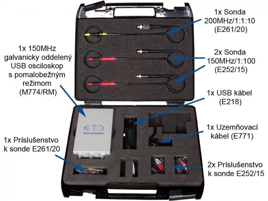
The kit is packed in a tough carry case that protects the instrument and accessories even during rough handling. Each part of the kit has its own place in polyethylene foam, which allows quick unpacking and packing and keeps the contents in place whatever the position of the case.

The kit for power system measurements contents

The kit for power system measurements contents

Cat. number
Description
M774/RM 1x 150 MHz isolated digital storage oscilloscope with roll mode
E218 1x USB 2.0/1,8m cable
E252/15 2x Oscilloscope probe 150 MHz/1:100, 1,2m
E261/20 1x Switchable oscilloscope probe 200 MHz/1:1:10, 1,2m
E771 1x Safety grounding cable
1x CD with software and user´s guide
1x Installation leaflet
1x Warning leaflet
1x Calibration certificate
1x Declaration of conformity
The kit for wide bandwidth measurements

The kit for wide bandwidth measurements

Thanks to the M595 oscilloscope, this kit is capable of measuring the frequencies up to 350MHz sampled with up to 1GS/s in real-time. The accessories are selected to allow measurements with input impedance of 10MOhm as well as measurements through 50Ohm coaxial cable

Using the fastest random interleaved sampling (RIS) mode (50GS/s) you can set the timebase as fast as 125ps/div.

Oscilloscope

The innovative design of the M595 oscilloscope is indeed extraordinary in this category. It offers extremely fast real time sampling rate (1GS/s for single channel, 500MS/s for both channels). Thanks to the precise construction, the input amplifiers offer up to 350MHz bandwidth. The device is powered from the wall adapter, which is equipped by the system of the replaceable plugs (usable in Europe, USA, UK and Australia).

Device uses metal casing, which withstand rough manipulation and is fully recyclable.

The M595 offers precise electronic engineering (as is usual in all ETC devices) and automated calibration processes during manufacturing. Each kit contains the traceable calibration certificate. The inputs withstand +-200V, which is quite rare in this category.

Since the M595 device uses USB 2.0 for communication (with automatic fallback to USB 1.1), the device provides you with high refresh rates comparable to the stand-alone devices.

Software

The basic package contains complex, yet easy to use, oscilloscope software (Scope). Scope allows you to easily control oscilloscope, use advanced functions (such as FFT, persistent display mode, mask testing) or export the data. The spectrum analyzer software is the part of the basic package as well (with the top frequency of 350MHz)

The roll mode (each kit contains the license for the device), allows you to acquire the data as fast as 5MS/s and store them directly to the hard drive. You can use either viewer to analyze the data or export tools to analyze data in third party applications.

Support

The ETC appreciates your decision to purchase ETC device, so we offer you the support for unlimited time. Feel free to ask our technicians for help with the measuring task you are currently working on.

The software is available on our website free of charge. Once we add new feature to the basic package, you will be able to download it for a free.

Packaging

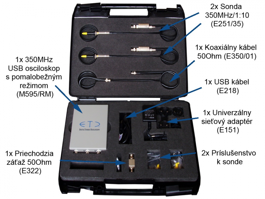
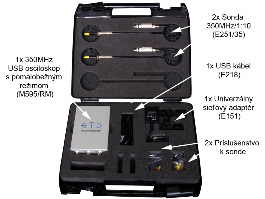
The kit for wide bandwidth measurements is stored in the tough carry case, which protects the device and accessories even in harsh conditions and manipulation. Each component has the place in the foam specifically designed for it. This provides you with the comfort of easy packing and unpacking and protects the components from falling out in non-standard positions of the case.

The kit for wide bandwidth measurements content

The kit for wide bandwidth measurements content

Cat. number
Description
M595/RM 1x 350 MHz digital storage oscilloscope with roll mode
E218 1x USB 2.0/1,8m cable
E151 1x Universal AC wall adapter 100 - 240 V, with European, UK, US and Australian plug
E251/35 2x Oscilloscope probe 350 MHz/1:10, 1m
E350/01 1x Coaxial cable 50 Ohm/1m
E322 1x Feed-through terminator 50 Ohm
1x CD with software and user´s guide
1x Installation leaflet
2x Warning leaflet
1x Calibration certificate
1x Declaration of conformity
M595 350MHz Digital Storage Oscilloscope

M595 350MHz Digital Storage Oscilloscope

  • USB 2.0 and USB 1.1 compatible
  • Dual channel with 350 MHz bandwidth
  • Deflection factor: 10mV/div to 5V/div in 1-2-5 sequence
  • Max real time sampling rate 1 GS/s (single channel), 500 MS/s (dual channel)
  • Max equivalent sampling rate 50 GS/s
  • Large internal memory: 32kS each channel
  • Software for Windows 98SE, Windows ME, Windows 2000, Windows XP, Windows Vista, Windows 7, Windows 8 and Windows 10(1903)

The M595 DSO is a member of Etc Measuring Lab 3 (EML3) family.

M595 is a dual channel USB oscilloscope compatible with USB 2.0 and USB 1.1 interface. The ease of installation and connection to computer makes M595 extremely portable. The device is connected to computer using standard USB 2.0 cable. It is powered from power adaptor compatible with European, UK, USA and Australian power system (part of the standard package).

The device inputs are accessible via BNC connectors and are compatible with standard probes (with minimum of 30 pF compensation range). Internal storage (32k per channel) is used as a fast data buffer to store a measured waveform.

The software is the part of the M595 package. In order to keep the device functions up to date, there is a latest version of software available on our website free of charge. The software provides you with possibilty to fully operate the device. All standard features of modern DSOs (hold acquisition process, hold-off, zoom etc.) and many more (saving/loading the waveforms for future use, export to clipboard, printing the results together with scope settings) are available.

The fast data transfer offers extremely rapid display refresh (creating an impression of analog instrument).

Four standard acquisition modes (AUTO, NORMAL, SINGLE, MANUAL) are available. The trigger event is created by dual level triggering system equipped with digital pulse length filter and event counter on each level. The channel A, channel B and the external trigger input can be activated as a triggering system source. The threshold of channel A and channel B trigger is settable in whole range of scope screen. The threshold of external trigger is fixed to about 1.5V and is TTL and CMOS compatible. This sophisticated triggering system allows displaying waveforms with very complicated trigger events (i.e. row of the video signal).

The time base in 1:1 display mode (no zoom) is settable from 1ns/div to 20ms/div in sequence of 1-2-5. It is possible to set the time base from 125ps/div to 1.28s/div using different zoom settings.

Installation guide in paper form and detailed user’s guide on CD are part of the M595 package. The tool tip help makes software easy to use.

Software works under Windows 98SE, Windows ME, Windows 2000, Windows XP, Windows Vista, Windows 7, Windows 8 and Windows 10(1903) operating systems. The oscilloscope screen can be resized according to your monitor resolution (minimum 800x600).

Two optional software packages are available: M590 Development kit, which will allow you to write your own application using the device and the M590 Roll mode, which will turn the oscilloscope into data logger.

M595 Performance Characteristics

Vertical deflection system

No of divisions 8
No of pixels per division 32
Deflection factor range 10mV/div to 5V/div in 1-2-5 sequence
Accuracy +- 2% of current value + 1 pixel
Resolution 8 bits (0,39%)
Frequency response (-3dB) DC: 0-300MHz, AC: 1.6Hz-300MHz on ranges 10mV/div to 50mV/div; DC: 0-350MHz, AC: 1.6Hz-350MHz on ranges 100mV/div to 5V/div
Step response rise time max. 1.2ns on ranges 10mV/div to 50mV/div, 1ns on rest of the vertical ranges
Channel isolation min. –40 dB
Resistance 1 MOhm +3%, -1%
Input resistance inaccuracy adjustment Digital for absolute accuracy +- 2% of current voltage + 1 pixel
Capacitance 28 pF +- 1pF
Zero setting accuracy +- 2% of the screen
Maximum input voltage +- 200V at 100 kHz or less

Triggering

System type Dual level
Trigger source for primary level selectable Channel A, Channel B or external trigger input
Trigger source for secondary level selectable Channel A, Channel B or external trigger input
Threshold setting Channel A and Channel B on the whole display range. External fixed on about 1.5V
Slope selection Leading or trailing edge independently on each source
Minimum trigger pulse period 4 ns
Minimum trigger pulse length 1.5 ns
Maximum voltage on external trigger input –10V to +13V at 20 kHz or less
Adjustments Digital filter with ability of setting the valid pulse length up to 32768*Ts for each level and counter of valid triggering events settable from 1 to 32767 for each level. HOLD-OFF settable up to 32768*Ts with selectable AUTO mode, to sample proper amount of data before trigger. (Ts – actual real time sampling period)

Data acquisition system

No of divisions 10
No of pixels per division 50
Mode of operation Sampling before and after trigger with continual selection of the trigger position
Record length settable from 1024 to 32768 (32k) samples for each channel
Time base range in 1:1 mode 1ns/d to 20ms/d in 1-2-5 sequence
Time base range using different ZOOM modes 125ps/d to 1.28s/d
Time base accuracy 0.01% to 20ns/d, 0.5% for 10ns/d to 1ns/d
Real time sampling frequency 2.5kHz to 1GHz single channel
2.5kHz to 500MHz dual channel
Equivalent sampling frequency 2.5kHz to 50GHz
Display range with respect to trigger event 32768 samples before and 32768 samples after trig. event in length of 32768 samples

Probe compensation generator

Output connector BNC, together with External trigger input
Output impedance 1 kOhm to parallel with 10nF and approx. 50 Ohm serial
Output waveform Pulse with 1:1 duty cycle
Frequency 1465 Hz
Output voltage (no load) 3.3V +- 5%

Synchronization output

Output connector BNC, together with External trigger input
Output waveform Leading edge of about 3V high pulse

Power

Power source USB interface and power adaptor 10V-18V DC (+ on central pin)
Max current USB: 0.85W (170mA), adaptor: 7W

Mechanical characteristics

Dimensions without feet and connectors 165 x 111 x 35 mm
Dimensions with feet and connectors 182 x 111 x 39 mm
Weight 560 g
K520 series kits (K521-K526)

K520 series kits (K521-K526)

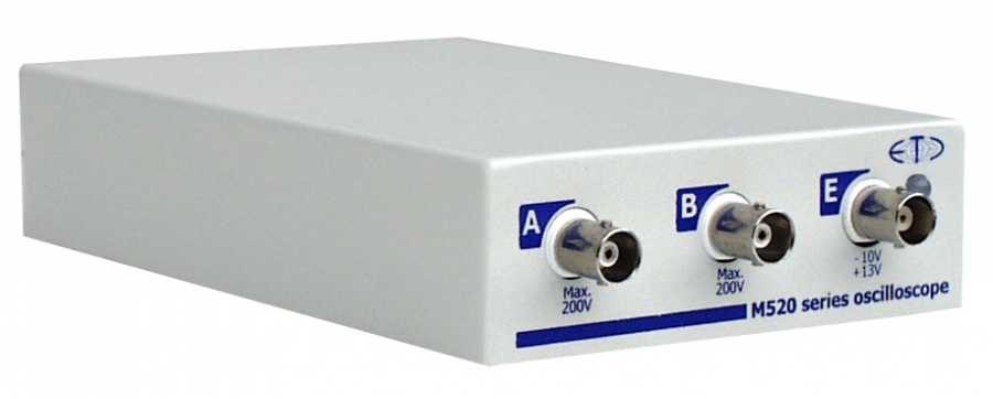
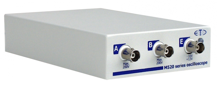
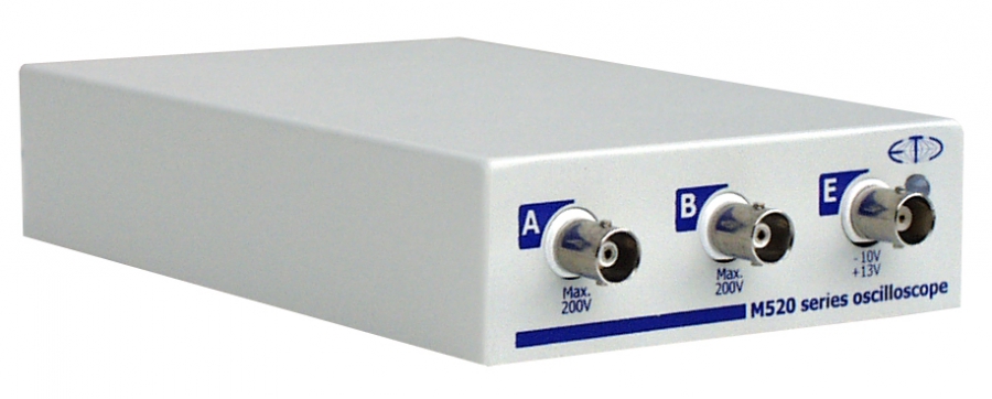
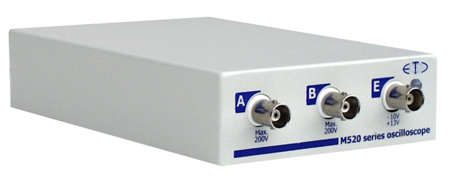
The M520 family offers six reliable devices usable for the common measurements. These devices are optimized for great price/performance ratio.

The devices use metal casing, which withstand rough manipulation and is fully recyclable.

The M520 series offers precise electronic engineering (as is usual in all ETC devices) and automated calibration processes during manufacturing. Each kit contains the traceable calibration certificate.

Since the M520 series devices use USB 2.0 for communication (with automatic fallback to USB 1.1), the device provides you with high refresh rates comparable to the stand-alone devices.

Software

The basic package contains complex, yet easy to use, oscilloscope software (Scope). Scope allows you to easily control oscilloscope, use advanced functions (such as FFT, persistent display mode, mask testing) or export the data. The spectrum analyzer software is the part of the basic package as well.

The roll mode (each kit contains the license for the device), allows you to acquire the data as fast as 5MS/s and store them directly to the hard drive. You can use either viewer to analyze the data or export tools to analyze data in third party applications.

Support

The ETC appreciates your decision to purchase ETC device, so we offer you the support for unlimited time. Feel free to ask our technicians for help with the measuring task you are currently working on.

The software is available on our website free of charge. Once we add new feature to the basic package, you will be able to download it for a free.

Following devices are available for this kit (together with appropriate pair of probes):

Type Channels Bandwidth Ranges Max sampling rate Max RIS sampling rate Timebase ranges Memory size Power source
M521 2 60MHz 10mV/div to 5V/div 50MS/s 5GS/s 1ns/d to 800ms/d 4K USB
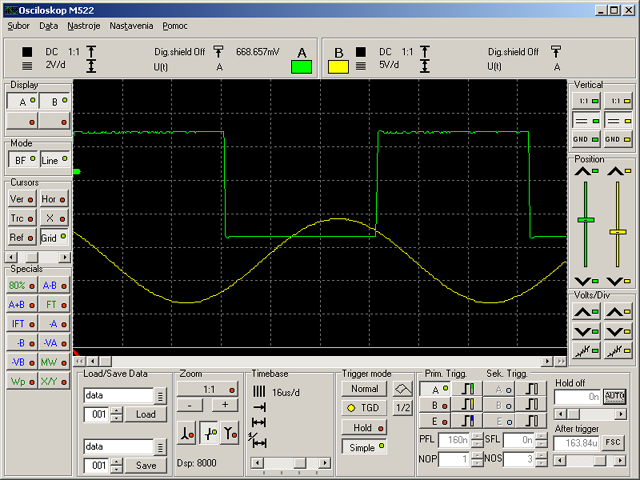
M522 2 60MHz 10mV/div to 5V/div 50MS/s 5GS/s 1ns/d to 1.6s/d 8K USB
M523 2 120MHz 10mV/div to 5V/div 100MS/s 10GS/s 500ps/d to 800ms/d 4K USB
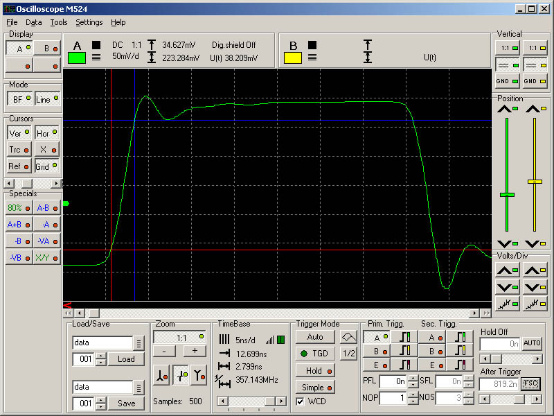
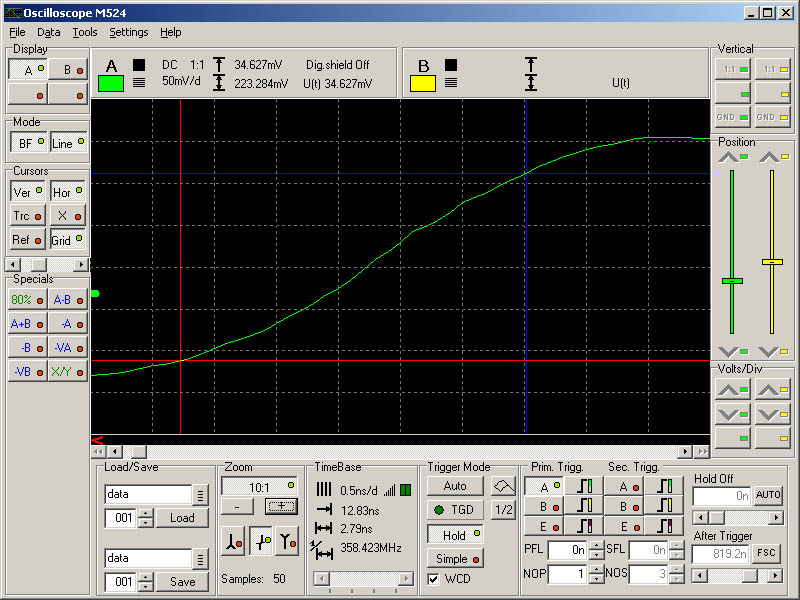
M524 2 120MHz 10mV/div to 5V/div 100MS/s 10GS/s 500ps/d to 1.6s/d 8K USB
M525 2 150MHz END OF PROD. 200MS/s 20GS/s 200ps/d to 800ms/d 4K USB
M526 2 150MHz 10mV/div to 5V/div 200MS/s 20GS/s 200ps/d to 1.6s/d 8K USB

Packaging

The K520 kits are stored in the tough carry case, which protects the device and accessories even in harsh conditions and manipulation. Each component has the place in the foam specifically designed for it. This provides you with the comfort of easy packing and unpacking and protects the components from falling out in non-standard positions of the case

M521 60MHz Digital Storage Oscilloscope

M521 60MHz Digital Storage Oscilloscope

  • USB 2.0 and USB 1.1 compatible
  • Dual channel with 60 MHz bandwidth
  • Deflection factor: 10mV/div to 5V/div in 1-2-5 sequence
  • Max real time sampling rate 50 MS/s
  • Max equivalent sampling rate 5 GS/s
  • Software for Windows 98SE, Windows ME, Windows 2000, Windows XP, Windows Vista, Windows 7, Windows 8 and Windows 10(1903)

The M521 DSO is a member of Etc Measuring Lab 3 (EML3) family.

The M521 is a dual channel USB oscilloscope compatible with USB 2.0 and USB 1.1 interface. The ease of installation and connection to computer makes M521 extremely portable. The device is connected to computer using standard USB 2.0 cable and is powered directly from computer. The maximum power consumption of 2.25W makes this instrument highly usable with battery-powered notebooks.

The device inputs are accessible via BNC connectors and are compatible with standard probes (with minimum of 32 pF compensation range). Internal storage (4K per channel) is used as a fast data buffer to store a measured waveform.

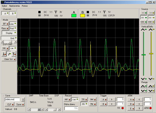
The software is the part of the M521 package. In order to keep the device functions up to date, there is a latest version of software available on our website free of charge. The software provides you with possibilty to fully operate the device. All standard features of modern DSOs (hold acquisition process, hold-off, zoom etc.) and many more (saving/loading the waveforms for future use, export to clipboard, printing the results together with scope settings) are available.

The fast data transfer offers extremely rapid display refresh (creating an impression of analog instrument).

Four standard acquisition modes (AUTO, NORMAL, SINGLE, MANUAL) are available. The trigger event is created by dual level triggering system equipped with digital pulse length filter and event counter on each level. The channel A, channel B and the external trigger input can be activated as a triggering system source. The threshold of channel A and channel B trigger is settable in whole range of scope screen. The threshold of external trigger is fixed to about 1.5V and is TTL and CMOS compatible. This sophisticated triggering system allows displaying waveforms with very complicated trigger events (i.e. selected row of the video signal).

The time base in 1:1 display mode (no zoom) is settable from 10ns/div to 100ms/div in sequence of 1-2-5. It is possible to set the time base from 1ns/div to 800ms/div using different zoom settings.

Installation guide in paper form and detailed user’s guide on CD are part of the M521 package. The tool tip help makes software easy to use.

Software works under Windows 98SE, Windows ME, Windows 2000, Windows XP, Windows Vista, Windows 7, Windows 8 and Windows 10(1903) operating systems. The oscilloscope screen can be resized according to your monitor resolution (minimum 800x600).

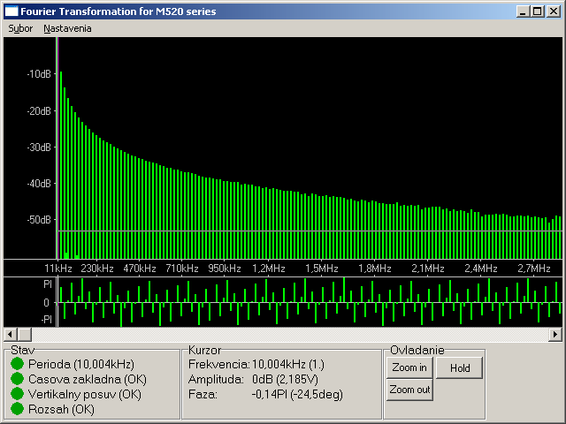
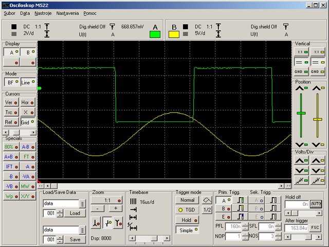
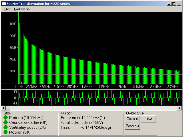
The spectrum analyzer software is the part of basic package. It analyzes signal on channel A and displays its frequency spectrum.

Two optional software packages are available: M520 Development kit, which will allow you to write your own application using the device and the M520 Roll mode, which will turn the oscilloscope into data logger.

M521 Performance Characteristics

Vertical deflection system

No of divisions 8
No of pixels per division 32
Deflection factor range 10mV/div to 5V/div in 1-2-5 sequence
Accuracy +- 2% of current value + 1 pixel
Resolution 8 bits (0,39%)
Frequency response (-3dB) DC: 0-60 MHz, AC: 1.2 Hz-60 MHz
Step response rise time max. 5.8 ns
Channel isolation min. –60 dB
Resistance 1 MOhm +5 %, -2 %
Input resistance inaccuracy adjustment Digital for absolute accuracy +- 2% of current voltage + 1 pixel
Capacitance 30 pF +- 2pF
Zero setting accuracy +- 2% of the screen
Maximum input voltage +- 200V at 100 kHz or less

Triggering

System type Dual level
Trigger source for primary level selectable Channel A, Channel B or external trigger input
Trigger source for secondary level selectable Channel A, Channel B or external trigger input
Threshold setting Channel A and Channel B on the whole display range. External fixed on about 1.5V
Slope selection Leading or trailing edge independently on each source
Minimum trigger pulse period 5 ns
Minimum trigger pulse length 2.5 ns
Maximum voltage on external trigger input –10V to +13V at 20 kHz or less
Adjustments Digital filter with ability of setting the valid pulse length up to 131072*Ts for each level and counter of valid triggering events settable from 1 to 32768 for each level. HOLD-OFF settable up to 131072*Ts with selectable AUTO mode, to sample proper amount of data before trigger. (Ts – actual real time sampling period)

Data acquisition system

No of divisions 10
No of pixels per division 50
Mode of operation Sampling before and after trigger with continual selection of the trigger position
Record length 4096 samples for each channel
Time base range in 1:1 mode 10 ns/d to 100 ms/d in 1-2-5 sequence
Time base range using different ZOOM modes 1 ns/d to 800 ms/d
Time base accuracy 0.01 % to 100ns/d, 0.5 % for 50ns/d to 5 ns/d
Real time sampling frequency 1kHz to 50 MHz
Equivalent sampling frequency 1kHz to 5 GHz
Display range with respect to trigger event 4094 samples before and 63000 samples after trig. event in length of 4096 samples

Probe compensation generator

Output connector BNC, together with External trigger input
Output impedance 1 kOhm to parallel with 10nF and approx. 50 Ohm serial
Output waveform Pulse with 1:1 duty cycle
Frequency 1465 Hz
Output voltage (no load) 3.3V +- 5%

Power

Power source USB interface via USB cable
Max current USB1.1: 350 mA, USB2.0: 450 mA

Mechanical characteristics

Dimensions without feet and connectors 165 x 111 x 35 mm
Dimensions with feet and connectors 182 x 111 x 39 mm
Weight 520 g
M522 60MHz Digital Storage Oscilloscope

M522 60MHz Digital Storage Oscilloscope

  • USB 2.0 and USB 1.1 compatible
  • Dual channel with 60 MHz bandwidth
  • Deflection factor: 10mV/div to 5V/div in 1-2-5 sequence
  • Max real time sampling rate 50 MS/s
  • Max equivalent sampling rate 5 GS/s
  • Software for Windows 98SE, Windows ME, Windows 2000, Windows XP, Windows Vista, Windows 7, Windows 8 and Windows 10(1903)

The M522 DSO is a member of Etc Measuring Lab 3 (EML3) family.

The M522 is a dual channel USB oscilloscope compatible with USB 2.0 and USB 1.1 interface. The ease of installation and connection to computer makes M522 extremely portable. The device is connected to computer using standard USB 2.0 cable and is powered directly from computer. The maximum power consumption of 2.25W makes this instrument highly usable with battery-powered notebooks.

The device inputs are accessible via BNC connectors and are compatible with standard probes (with minimum of 32 pF compensation range). Internal storage (8K per channel) is used as a fast data buffer to store a measured waveform.

The software is the part of the M522 package. In order to keep the device functions up to date, there is a latest version of software available on our website free of charge. The software provides you with possibilty to fully operate the device. All standard features of modern DSOs (hold acquisition process, hold-off, zoom etc.) and many more (saving/loading the waveforms for future use, export to clipboard, printing the results together with scope settings) are available.

The fast data transfer offers extremely rapid display refresh (creating an impression of analog instrument).

Four standard acquisition modes (AUTO, NORMAL, SINGLE, MANUAL) are available. The trigger event is created by dual level triggering system equipped with digital pulse length filter and event counter on each level. The channel A, channel B and the external trigger input can be activated as a triggering system source. The threshold of channel A and channel B trigger is settable in whole range of scope screen. The threshold of external trigger is fixed to about 1.5V and is TTL and CMOS compatible. This sophisticated triggering system allows displaying waveforms with very complicated trigger events (i.e. selected row of the video signal).

The time base in 1:1 display mode (no zoom) is settable from 10ns/div to 100ms/div in sequence of 1-2-5. It is possible to set the time base from 1ns/div to 1.6s/div using different zoom settings.

Installation guide in paper form and detailed user’s guide on CD are part of the M522 package. The tool tip help makes software easy to use.

Software works under Windows 98SE, Windows ME, Windows 2000, Windows XP, Windows Vista, Windows 7, Windows 8 and Windows 10(1903) operating systems. The oscilloscope screen can be resized according to your monitor resolution (minimum 800x600).

The spectrum analyzer software is the part of basic package. It analyzes signal on channel A and displays its frequency spectrum.

Two optional software packages are available: M520 Development kit, which will allow you to write your own application using the device and the M520 Roll mode, which will turn the oscilloscope into data logger.

M522 Performance Characteristics

Vertical deflection system

No of divisions 8
No of pixels per division 32
Deflection factor range 10mV/div to 5V/div in 1-2-5 sequence
Accuracy +- 2% of current value + 1 pixel
Resolution 8 bits (0,39%)
Frequency response (-3dB) DC: 0-60 MHz, AC: 1.2 Hz-60 MHz
Step response rise time max. 5.8 ns
Channel isolation min. –60 dB
Resistance 1 MOhm +5 %, -2 %
Input resistance inaccuracy adjustment Digital for absolute accuracy +- 2% of current voltage + 1 pixel
Capacitance 30 pF +- 2pF
Zero setting accuracy +- 2% of the screen
Maximum input voltage +- 200V at 100 kHz or less

Triggering

System type Dual level
Trigger source for primary level selectable Channel A, Channel B or external trigger input
Trigger source for secondary level selectable Channel A, Channel B or external trigger input
Threshold setting Channel A and Channel B on the whole display range. External fixed on about 1.5V
Slope selection Leading or trailing edge independently on each source
Minimum trigger pulse period 5 ns
Minimum trigger pulse length 2.5 ns
Maximum voltage on external trigger input –10V to +13V at 20 kHz or less
Adjustments Digital filter with ability of setting the valid pulse length up to 131072*Ts for each level and counter of valid triggering events settable from 1 to 32768 for each level. HOLD-OFF settable up to 131072*Ts with selectable AUTO mode, to sample proper amount of data before trigger. (Ts – actual real time sampling period)

Data acquisition system

No of divisions 10
No of pixels per division 50
Mode of operation Sampling before and after trigger with continual selection of the trigger position
Record length 8192 samples for each channel
Time base range in 1:1 mode 10 ns/d to 100 ms/d in 1-2-5 sequence
Time base range using different ZOOM modes 1 ns/d to 1.6 s/d
Time base accuracy 0.01 % to100ns/d, 0.5 % for 50ns/d to 5 ns/d
Real time sampling frequency 1kHz to 50 MHz
Equivalent sampling frequency 1kHz to 5 GHz
Display range with respect to trigger event 8190 samples before and 63000 samples after trig. event in length of 8192 samples

Probe compensation generator

Output connector BNC, together with External trigger input
Output impedance 1 kOhm to parallel with 10nF and approx. 50 Ohm serial
Output waveform Pulse with 1:1 duty cycle
Frequency 1465 Hz
Output voltage (no load) 3.3V +- 5%

Power

Power source USB interface via USB cable
Max current USB1.1: 350 mA, USB2.0: 450 mA

Mechanical characteristics

Dimensions without feet and connectors 165 x 111 x 35 mm
Dimensions with feet and connectors 182 x 111 x 39 mm
Weight 520 g

Roll mode

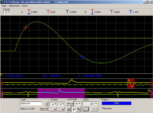
If you need to perform measurements longer than the internal device buffer, the Roll mode is the right application for you. It turns the M520 series oscilloscope to data logger with sampling rate from 50S/s to 5Ms/s (50S/s to 250kS/s if the device is connected via USB 1.1). Please note, that very fast computer is required for sampling rates higher than 500kS/s. The measured data are directly stored to disc. The capacity of the data file is limited by the capacity of your hard disk drive or additional limitations of your operating system (if there are any). The measured data are visible during the acquisition and also can be viewed using the Roll mode viewer.

The Roll Mode software package consists of two applications.

m520rm

The data acquisition application measures data and stores them to the hard disk drive. These can be viewed using the data viewer.

m520rmvw

The Roll Mode is optional accessory (not for free). It is possible to purchase it directly with the device or separately for use with instrument you already own.

M523 120MHz Digital Storage Oscilloscope

M523 120MHz Digital Storage Oscilloscope

  • USB 2.0 and USB 1.1 compatible
  • Dual channel with 120 MHz bandwidth
  • Deflection factor: 10mV/div to 5V/div in 1-2-5 sequence
  • Max real time sampling rate 100 MS/s
  • Max equivalent sampling rate 10 GS/s
  • Software for Windows 98SE, Windows ME, Windows 2000, Windows XP, Windows Vista, Windows 7, Windows 8 and Windows 10(1903)

The M523 DSO is a member of Etc Measuring Lab 3 (EML3) family.

The M523 is a dual channel USB oscilloscope compatible with USB 2.0 and USB 1.1 interface. The ease of installation and connection to computer makes M523 extremely portable. The device is connected to computer using standard USB 2.0 cable and is powered directly from computer. The maximum power consumption of 2.25W makes this instrument highly usable with battery-powered notebooks.

The device inputs are accessible via BNC connectors and are compatible with standard probes (with minimum of 32 pF compensation range). Internal storage (4K per channel) is used as a fast data buffer to store a measured waveform.

The software is the part of the M523 package. In order to keep the device functions up to date, there is a latest version of software available on our website free of charge. The software provides you with possibilty to fully operate the device. All standard features of modern DSOs (hold acquisition process, hold-off, zoom etc.) and many more (saving/loading the waveforms for future use, export to clipboard, printing the results together with scope settings) are available.

The fast data transfer offers extremely rapid display refresh (creating an impression of analog instrument).

Four standard acquisition modes (AUTO, NORMAL, SINGLE, MANUAL) are available. The trigger event is created by dual level triggering system equipped with digital pulse length filter and event counter on each level. The channel A, channel B and the external trigger input can be activated as a triggering system source. The threshold of channel A and channel B trigger is settable in whole range of scope screen. The threshold of external trigger is fixed to about 1.5V and is TTL and CMOS compatible. This sophisticated triggering system allows displaying waveforms with very complicated trigger events (i.e. selected row of the video signal).

The time base in 1:1 display mode (no zoom) is settable from 5ns/div to 100ms/div in sequence of 1-2-5. It is possible to set the time base from 500ps/div to 800ms/div using different zoom settings.

Installation guide in paper form and detailed user’s guide on CD are part of the M523 package. The tool tip help makes software easy to use.

Software works under Windows 98SE, Windows ME, Windows 2000, Windows XP, Windows Vista, Windows 7, Windows 8 and Windows 10(1903) operating systems. The oscilloscope screen can be resized according to your monitor resolution (minimum 800x600).

The spectrum analyzer software is the part of basic package. It analyzes signal on channel A and displays its frequency spectrum.

Two optional software packages are available: M520 Development kit, which will allow you to write your own application using the device and the M520 Roll mode, which will turn the oscilloscope into data logger.

M523 Performance Characteristics

Vertical deflection system

No of divisions 8
No of pixels per division 32
Deflection factor range 10mV/div to 5V/div in 1-2-5 sequence
Accuracy +- 2% of current value + 1 pixel
Resolution 8 bits (0,39%)
Frequency response (-3dB) DC: 0-120 MHz, AC: 1.2 Hz-120 MHz
Step response rise time max. 2.9 ns
Channel isolation min. –60 dB
Resistance 1 MOhm +5 %, -2 %
Input resistance inaccuracy adjustment Digital for absolute accuracy +- 2% of current voltage + 1 pixel
Capacitance 30 pF +- 2pF
Zero setting accuracy +- 2% of the screen
Maximum input voltage +- 200V at 100 kHz or less

Triggering

System type Dual level
Trigger source for primary level selectable Channel A, Channel B or external trigger input
Trigger source for secondary level selectable Channel A, Channel B or external trigger input
Threshold setting Channel A and Channel B on the whole display range. External fixed on about 1.5V
Slope selection Leading or trailing edge independently on each source
Minimum trigger pulse period 5 ns
Minimum trigger pulse length 2.5 ns
Maximum voltage on external trigger input –10V to +13V at 20 kHz or less
Adjustments Digital filter with ability of setting the valid pulse length up to 131072*Ts for each level and counter of valid triggering events settable from 1 to 32768 for each level. HOLD-OFF settable up to 131072*Ts with selectable AUTO mode, to sample proper amount of data before trigger. (Ts – actual real time sampling period)

Data acquisition system

No of divisions 10
No of pixels per division 50
Mode of operation Sampling before and after trigger with continual selection of the trigger position
Record length 4096 samples for each channel
Time base range in 1:1 mode 5 ns/d to 100 ms/d in 1-2-5 sequence
Time base range using different ZOOM modes 500 ps/d to 800 ms/d
Time base accuracy 0.01 % to100ns/d, 0.5 % for 50ns/d to 5 ns/d
Real time sampling frequency 1kHz to 100 MHz
Equivalent sampling frequency 1kHz to 10 GHz
Display range with respect to trigger event 4094 samples before and 63000 samples after trig. event in length of 4096 samples

Probe compensation generator

Output connector BNC, together with External trigger input
Output impedance 1 kOhm to parallel with 10nF and approx. 50 Ohm serial
Output waveform Pulse with 1:1 duty cycle
Frequency 1465 Hz
Output voltage (no load) 3.3V +- 5%

Power

Power source USB interface via USB cable
Max current USB1.1: 350 mA, USB2.0: 450 mA

Mechanical characteristics

Dimensions without feet and connectors 165 x 111 x 35 mm
Dimensions with feet and connectors 182 x 111 x 39 mm
Weight 520 g

M524 Performance Characteristics

Vertical deflection system

No of divisions 8
No of pixels per division 32
Deflection factor range 10mV/div to 5V/div in 1-2-5 sequence
Accuracy +- 2% of current value + 1 pixel
Resolution 8 bits (0,39%)
Frequency response (-3dB) DC: 0-120 MHz, AC: 1.2 Hz-120 MHz
Step response rise time max. 2.9 ns
Channel isolation min. –60 dB
Resistance 1 MOhm +5 %, -2 %
Input resistance inaccuracy adjustment Digital for absolute accuracy +- 2% of current voltage + 1 pixel
Capacitance 30 pF +- 2pF
Zero setting accuracy +- 2% of the screen
Maximum input voltage +- 200V at 100 kHz or less

Triggering

System type Dual level
Trigger source for primary level selectable Channel A, Channel B or external trigger input
Trigger source for secondary level selectable Channel A, Channel B or external trigger input
Threshold setting Channel A and Channel B on the whole display range. External fixed on about 1.5V
Slope selection Leading or trailing edge independently on each source
Minimum trigger pulse period 5 ns
Minimum trigger pulse length 2.5 ns
Maximum voltage on external trigger input –10V to +13V at 20 kHz or less
Adjustments Digital filter with ability of setting the valid pulse length up to 131072*Ts for each level and counter of valid triggering events settable from 1 to 32768 for each level. HOLD-OFF settable up to 131072*Ts with selectable AUTO mode, to sample proper amount of data before trigger. (Ts – actual real time sampling period)

Data acquisition system

No of divisions 10
No of pixels per division 50
Mode of operation Sampling before and after trigger with continual selection of the trigger position
Record length 8192 samples for each channel
Time base range in 1:1 mode 5 ns/d to 100 ms/d in 1-2-5 sequence
Time base range using different ZOOM modes 500 ps/d to 1.6 s/d
Time base accuracy 0.01 % to100ns/d, 0.5 % for 50ns/d to 5 ns/d
Real time sampling frequency 1kHz to 100 MHz
Equivalent sampling frequency 1kHz to 10 GHz
Display range with respect to trigger event 8190 samples before and 63000 samples after trig. event in length of 8192 samples

Probe compensation generator

Output connector BNC, together with External trigger input
Output impedance 1 kOhm to parallel with 10nF and approx. 50 Ohm serial
Output waveform Pulse with 1:1 duty cycle
Frequency 1465 Hz
Output voltage (no load) 3.3V +- 5%

Power

Power source USB interface via USB cable
Max current USB1.1: 350 mA, USB2.0: 450 mA

Mechanical characteristics

Dimensions without feet and connectors 165 x 111 x 35 mm
Dimensions with feet and connectors 182 x 111 x 39 mm
Weight 520 g
M524 120MHz Digital Storage Oscilloscope

M524 120MHz Digital Storage Oscilloscope

END OF PRODUCTION
  • USB 2.0 and USB 1.1 compatible
  • Dual channel with 120 MHz bandwidth
  • Deflection factor: 10mV/div to 5V/div in 1-2-5 sequence
  • Max real time sampling rate 100 MS/s
  • Max equivalent sampling rate 10 GS/s
  • Software for Windows 98SE, Windows ME, Windows 2000, Windows XP, Windows Vista, Windows 7, Windows 8 and Windows 10(1903)

The M524 DSO is a member of Etc Measuring Lab 3 (EML3) family.

The M524 is a dual channel USB oscilloscope compatible with USB 2.0 and USB 1.1 interface. The ease of installation and connection to computer makes M524 extremely portable. The device is connected to computer using standard USB 2.0 cable and is powered directly from computer. The maximum power consumption of 2.25W makes this instrument highly usable with battery-powered notebooks.

The device inputs are accessible via BNC connectors and are compatible with standard probes (with minimum of 32 pF compensation range). Internal storage (8K per channel) is used as a fast data buffer to store a measured waveform.

The software is the part of the M524 package. In order to keep the device functions up to date, there is a latest version of software available on our website free of charge. The software provides you with possibilty to fully operate the device. All standard features of modern DSOs (hold acquisition process, hold-off, zoom etc.) and many more (saving/loading the waveforms for future use, export to clipboard, printing the results together with scope settings) are available.

The fast data transfer offers extremely rapid display refresh (creating an impression of analog instrument).

Four standard acquisition modes (AUTO, NORMAL, SINGLE, MANUAL) are available. The trigger event is created by dual level triggering system equipped with digital pulse length filter and event counter on each level. The channel A, channel B and the external trigger input can be activated as a triggering system source. The threshold of channel A and channel B trigger is settable in whole range of scope screen. The threshold of external trigger is fixed to about 1.5V and is TTL and CMOS compatible. This sophisticated triggering system allows displaying waveforms with very complicated trigger events (i.e. selected row of the video signal).

The time base in 1:1 display mode (no zoom) is settable from 5ns/div to 100ms/div in sequence of 1-2-5. It is possible to set the time base from 500ps/div to 1.6s/div using different zoom settings.

Installation guide in paper form and detailed user’s guide on CD are part of the M524 package. The tool tip help makes software easy to use.

Software works under Windows 98SE, Windows ME, Windows 2000, Windows XP, Windows Vista, Windows 7, Windows 8 and Windows 10(1903) operating systems. The oscilloscope screen can be resized according to your monitor resolution (minimum 800x600).

The spectrum analyzer software is the part of basic package. It analyzes signal on channel A and displays its frequency spectrum.

Two optional software packages are available: M520 Development kit, which will allow you to write your own application using the device and the M520 Roll mode, which will turn the oscilloscope into data logger.

M525 150MHz Digital Storage Oscilloscope

M525 150MHz Digital Storage Oscilloscope

DISCONTINUED
  • Compatible with USB 2.0 and USB 1.1
  • Two channels with 150MHz bandwidth
  • Sensitivity: 10mV/div to 5V/div in 1-2-5 steps
  • Maximum real-time sampling rate 200MS/s
  • Maximum equivalent sampling rate 20GS/s
  • Software for Windows 98SE, Windows ME, Windows 2000, Windows XP, Windows Vista, Windows 7, Windows 8 and Windows 10 (1903)

The M525 digital storage oscilloscope is a member of the ETC Measuring Lab 3 (EML3) family.

The M525 is a two-channel oscilloscope connected via USB 2.0 or USB 1.1. Easy installation and connection to the computer make the M525 well suited for mobile use. The device is connected to the computer with a standard USB cable and is powered from it. With a maximum power consumption of 2.25W it works well with a battery-powered notebook.

The inputs use BNC connectors and are compatible with standard probes (with a minimum compensation range of 32pF). The internal memory (4K per channel) is used as a fast buffer for the measured waveforms.

The software is included in the M525 package. The latest version is available free of charge on our website. All standard functions of modern digital oscilloscopes (pause, delayed acquisition, zoom etc.) and many more (saving/loading waveforms for later use, export to the clipboard, printing a measurement together with the oscilloscope settings) are available.

The high transfer rate allows frequent screen updates (giving the feel of an analog oscilloscope).

Four acquisition modes are available (AUTO, NORMAL, SINGLE, MANUAL). Triggering is controlled by a two-level trigger system with a digital pulse filter and an occurrence counter on each level. Channel A, channel B and the external input can be selected as the trigger source. The trigger level of channels A and B can be set anywhere within the oscilloscope screen. The threshold of the external input is approximately 1.5V and is TTL and CMOS compatible. This sophisticated system allows synchronization with complex waveforms (e.g. selecting a line of a video signal).

In 1:1 zoom mode the time base can be set from 2ns/div to 100ms/div in 1-2-5 steps. Using other zoom modes, the time base can be set from 200ps/div to 800ms/div.

The M525 package includes a printed installation guide and a detailed user's guide on CD. Context help is integrated into the software.

The software runs under Windows 98SE, Windows ME, Windows 2000, Windows XP, Windows Vista, Windows 7, Windows 8 and Windows 10 (1903). The size of the oscilloscope screen adapts to the monitor resolution (minimum 800x600).

The Spectrum analyzer software is part of the basic package. It analyses the signal on channel A and displays its frequency spectrum.

Two optional software packages are available: the M520 Development kit, which allows you to create your own applications using the M520 devices, and the M520 Roll mode, which turns the oscilloscope into a data recorder.

M525 Performance Characteristics

Vertical deflection system

No of divisions 8
No of pixels per division 32
Deflection factor range 10mV/div to 5V/div in 1-2-5 sequence
Accuracy +- 2% of current value + 1 pixel
Resolution 8 bits (0,39%)
Frequency response (-3dB) DC: 0-150 MHz, AC: 1.2 Hz-150 MHz
Step response rise time max. 2.4 ns
Channel isolation min. –60 dB
Resistance 1 MOhm +5 %, -2 %
Input resistance inaccuracy adjustment Digital for absolute accuracy +- 2% of current voltage + 1 pixel
Capacitance 30 pF +- 2pF
Zero setting accuracy +- 2% of the screen
Maximum input voltage +- 200V at 100 kHz or less

Triggering

System type Dual level
Trigger source for primary level selectable Channel A, Channel B or external trigger input
Trigger source for secondary level selectable Channel A, Channel B or external trigger input
Threshold setting Channel A and Channel B on the whole display range. External fixed on about 1.5V
Slope selection Leading or trailing edge independently on each source
Minimum trigger pulse period 5 ns
Minimum trigger pulse length 2.5 ns
Maximum voltage on external trigger input –10V to +13V at 20 kHz or less
Adjustments Digital filter with ability of setting the valid pulse length up to 131072*Ts for each level and counter of valid triggering events settable from 1 to 32768 for each level. HOLD-OFF settable up to 131072*Ts with selectable AUTO mode, to sample proper amount of data before trigger. (Ts – actual real time sampling period)

Data acquisition system

No of divisions 10
No of pixels per division 40
Mode of operation Sampling before and after trigger with continual selection of the trigger position
Record length 4096 samples for each channel
Time base range in 1:1 mode 2 ns/d to 100 ms/d in 1-2-5 sequence
Time base range using different ZOOM modes 200 ps/d to 800 ms/d
Time base accuracy 0.01 % to 100ns/d, 0.5 % for 50ns/d to 5 ns/d
Real time sampling frequency 1kHz to 200 MHz
Equivalent sampling frequency 1kHz to 20 GHz
Display range with respect to trigger event 4094 samples before and 63000 samples after trig. event in length of 4096 samples

Probe compensation generator

Output connector BNC, together with External trigger input
Output impedance 1 kOhm to parallel with 10nF and approx. 50 Ohm serial
Output waveform Pulse with 1:1 duty cycle
Frequency 1465 Hz
Output voltage (no load) 3.3V +- 5%

Power

Power source USB interface via USB cable
Max current USB1.1: 350 mA, USB2.0: 450 mA

Mechanical characteristics

Dimensions without feet and connectors 165 x 111 x 35 mm
Dimensions with feet and connectors 182 x 111 x 39 mm
Weight 520 g
M526 150MHz Digital Storage Oscilloscope

M526 150MHz Digital Storage Oscilloscope

  • USB 2.0 and USB 1.1 compatible
  • Dual channel with 150 MHz bandwidth
  • Deflection factor: 10mV/div to 5V/div in 1-2-5 sequence
  • Max real time sampling rate 200 MS/s
  • Max equivalent sampling rate 20 GS/s
  • Software for Windows 98SE, Windows ME, Windows 2000, Windows XP, Windows Vista, Windows 7, Windows 8 and Windows 10(1903)

The M526 DSO is a member of Etc Measuring Lab 3 (EML3) family.

The M526 is a dual channel USB oscilloscope compatible with USB 2.0 and USB 1.1 interface. The ease of installation and connection to computer makes M526 extremely portable. The device is connected to computer using standard USB 2.0 cable and is powered directly from computer. The maximum power consumption of 2.25W makes this instrument highly usable with battery-powered notebooks.

The device inputs are accessible via BNC connectors and are compatible with standard probes (with minimum of 32 pF compensation range). Internal storage (8K per channel) is used as a fast data buffer to store a measured waveform.

The software is the part of the M526 package. In order to keep the device functions up to date, there is a latest version of software available on our website free of charge. The software provides you with possibilty to fully operate the device. All standard features of modern DSOs (hold acquisition process, hold-off, zoom etc.) and many more (saving/loading the waveforms for future use, export to clipboard, printing the results together with scope settings) are available.

The fast data transfer offers extremely rapid display refresh (creating an impression of analog instrument).

Four standard acquisition modes (AUTO, NORMAL, SINGLE, MANUAL) are available. The trigger event is created by dual level triggering system equipped with digital pulse length filter and event counter on each level. The channel A, channel B and the external trigger input can be activated as a triggering system source. The threshold of channel A and channel B trigger is settable in whole range of scope screen. The threshold of external trigger is fixed to about 1.5V and is TTL and CMOS compatible. This sophisticated triggering system allows displaying waveforms with very complicated trigger events (i.e. selected row of the video signal).

The time base in 1:1 display mode (no zoom) is settable from 2ns/div to 100ms/div in sequence of 1-2-5. It is possible to set the time base from 200ps/div to 1.6s/div using different zoom settings.

Installation guide in paper form and detailed user’s guide on CD are part of the M526 package. The tool tip help makes software easy to use.

Software works under Windows 98SE, Windows ME, Windows 2000, Windows XP, Windows Vista, Windows 7, Windows 8 and Windows 10(1903) operating systems. The oscilloscope screen can be resized according to your monitor resolution (minimum 800x600).

The spectrum analyzer software is the part of basic package. It analyzes signal on channel A and displays its frequency spectrum.

Two optional software packages are available: M520 Development kit, which will allow you to write your own application using the device and the M520 Roll mode, which will turn the oscilloscope into data logger.

M526 Performance Characteristics

Vertical deflection system

No of divisions 8
No of pixels per division 32
Deflection factor range 10mV/div to 5V/div in 1-2-5 sequence
Accuracy +- 2% of current value + 1 pixel
Resolution 8 bits (0,39%)
Frequency response (-3dB) DC: 0-150 MHz, AC: 1.2 Hz-150 MHz
Step response rise time max. 2.4 ns
Channel isolation min. –60 dB
Resistance 1 MOhm +5 %, -2 %
Input resistance inaccuracy adjustment Digital for absolute accuracy +- 2% of current voltage + 1 pixel
Capacitance 30 pF +- 2pF
Zero setting accuracy +- 2% of the screen
Maximum input voltage +- 200V at 100 kHz or less

Triggering

System type Dual level
Trigger source for primary level selectable Channel A, Channel B or external trigger input
Trigger source for secondary level selectable Channel A, Channel B or external trigger input
Threshold setting Channel A and Channel B on the whole display range. External fixed on about 1.5V
Slope selection Leading or trailing edge independently on each source
Minimum trigger pulse period 5 ns
Minimum trigger pulse length 2.5 ns
Maximum voltage on external trigger input –10V to +13V at 20 kHz or less
Adjustments Digital filter with ability of setting the valid pulse length up to 131072*Ts for each level and counter of valid triggering events settable from 1 to 32768 for each level. HOLD-OFF settable up to 131072*Ts with selectable AUTO mode, to sample proper amount of data before trigger. (Ts – actual real time sampling period)

Data acquisition system

No of divisions 10
No of pixels per division 40
Mode of operation Sampling before and after trigger with continual selection of the trigger position
Record length 8192 samples for each channel
Time base range in 1:1 mode 2 ns/d to 100 ms/d in 1-2-5 sequence
Time base range using different ZOOM modes 200 ps/d to 1.6 s/d
Time base accuracy 0.01 % to 100ns/d, 0.5 % for 50ns/d to 5 ns/d
Real time sampling frequency 1kHz to 200 MHz
Equivalent sampling frequency 1kHz to 20 GHz
Display range with respect to trigger event 8190 samples before and 63000 samples after trig. event in length of 8192 samples

Probe compensation generator

Output connector BNC, together with External trigger input
Output impedance 1 kOhm to parallel with 10nF and approx. 50 Ohm serial
Output waveform Pulse with 1:1 duty cycle
Frequency 1465 Hz
Output voltage (no load) 3.3V +- 5%

Power

Power source USB interface via USB cable
Max current USB1.1: 350 mA, USB2.0: 450 mA

Mechanical characteristics

Dimensions without feet and connectors 165 x 111 x 35 mm
Dimensions with feet and connectors 182 x 111 x 39 mm
Weight 520 g
K531 - Arbitrary waveform generator kit

K531 - Arbitrary waveform generator kit

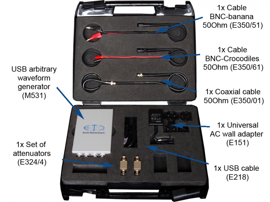
The kit contains the M531 AWG (Arbitrary waveform generator), which can be (together with included accessories) used in wide range of applications.

Device uses metal casing, which withstand rough manipulation and is fully recyclable.

The M531 offers precise electronic engineering (as is usual in all ETC devices) and automated calibration processes during manufacturing. Each kit contains the traceable calibration certificate.

Device is also equipped with the high-level output capable of generating signal with 25V amplitude. The high-level output is available once the device is powered from the wall adapter, which is equipped by the system of the replaceable plugs (usable in Europe, USA, UK and Australia).

Support

The ETC appreciates your decision to purchase ETC device, so we offer you the support for unlimited time. Feel free to ask our technicians for help with the measuring task you are currently working on.

The software is available on our website free of charge. Once we add new feature to the basic package, you will be able to download it for a free.

Packaging

The K531 kit is stored in the tough carry case, which protects the device and accessories even in harsh conditions and manipulation. Each component has the place in the foam specifically designed for it. This provides you with the comfort of easy packing and unpacking and protects the components from falling out in non-standard positions of the case.

K531 - Contents

K531 - Contents

Cat. number
Description
M531 1x USB arbitrary waveform generator
E218 1x USB 2.0/1,8m cable
E151 1x Universal AC wall adapter 100 - 240 V, with European, UK, US and Australian plug
E350/01 1x Coaxial cable 50 Ohm/1m
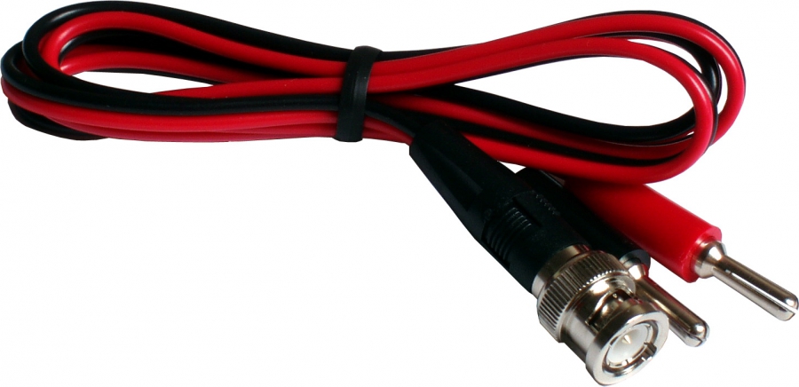
E350/51 1x Cable BNC-Banana 50 Ohm/1m
E324/4 1x Set of attenuators
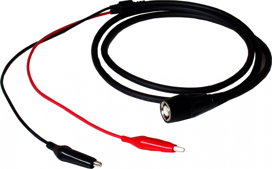
E350/61 1x Cable BNC-Crocodiles 50 Ohm/1m
1x CD with software and user´s guide
1x Installation leaflet
2x Warning leaflet
1x Calibration certificate
1x Declaration of conformity
M531 Arbitrary Waveform Generator

M531 Arbitrary Waveform Generator

  • USB 2.0 and USB 1.1 compatible
  • Fast low level output
  • High level output (up to 50Vpp)
  • 12 bit DA converter
  • Sample rate up to 100 MS/s
  • Powered from USB (external power is required for high level operation only)
  • Small dimensions and weight
  • Software for Windows 98SE, Windows ME, Windows 2000, Windows XP, Windows Vista, Windows 7, Windows 8 or Windows 10(1903)

The M531 AWG is a member of Etc Measuring Lab 3 (EML3) family.

The M531 is a single channel USB arbitrary waveform generator compatible with USB 2.0 and USB 1.1 interface. The generator has two outputs: both generate same waveform, but with different peak-peak voltage. The low level output has 50ohm output impedance and maximal peak-peak voltage of 9V. There is no external power supply required to enable low level output (it is powered from USB bus).

The high level output has 600 ohm output impedance and maximal peak-peak voltage of 50V. External power supply (part of the package) is required to enable this output.

The powerful software is a part of package. All commonly used features are located in the main window and are easily accessible by mouse. The software is designed to make operation as comfortable and intuitive as possible.

The waveform library contains several pre-defined waveform (Sine, Triangle, Saw, Square). You can create new waveform (or modify existing one) by integrated editors (freeform editor, math editor, standard waves editor). It is possible to import data from the ASCII format (for example Matlab, Excel or any other application, which supports this format).

Optional software package is available: M530 Development kit, which will allow you to write your own application using the device.

M531 - Performance characteristics

Outputs

Number of channels 1
Number of outputs 2, low and high level (L and H)
Output attenuator Settable to 0 or -20dB on L output
Max. output voltage, output L, no load -4.5V to 4.5V (9Vpp) attenuator set to 0dB
-450mV to 450mV (900mVpp) attenuator set to -20dB
Max. output voltage, output H, no load -25V to 25V (50Vpp)
Recommended range of output voltage setting, output L, no load 800mVpp to 9Vpp attenuator set to 0dB
80mVpp to 900mVpp attenuator set to -20dB
Recommended range of output voltage setting, output H, no load 4.6Vpp to 50Vpp
Output voltage setting step, output L, no load less than 2.5mV (attenuator set to 0dB)
less than 250uV (attenuator set to -20 dB)
Output voltage setting step, output H, no load less than 13mV
Output voltage setting accuracy Output L: +-2% from the actual value in recommended range up to 10 MHz.
Output H: +-2.5% from actual value in recommended range up to 100 kHz.
+-5% from 100kHz to 200kHz
Output voltage shift range, output L, no load +-1.5V attenuator set to 0dB
+-150mV attenuator set to -20dB
Output voltage shift range, output H, no load +-8V
Shift setting accuracy, output L +-1.5% from whole range
Shift setting accuracy, output H +-2% from whole range
Output resistance, output L 50Ohm
Output resistance, output H 600Ohm
Output resistance accuracy, output L +-1.5% attenuator set to 0dB
+2%, -0.5%, attenuator set to -20 dB
Output resistance accuracy, output H +-1.5%
Filter Settable to 20MHz, 40MHz or off
Output pulse edge length, output L less than 10ns, filter off
Output pulse edge length, output H less than 2.5us
Short circuit protection Unlimited

Waveform generation

Waveform memory length 8192 samples in standard mode, maximally 16384 samples in arbitrary mode
Frequency setting step less than 0.003% from actual value
Frequency accuracy 0.01% from actual value
Maximum output update rate 100 000 000 samples/s
Output waveform period length 2mHz to 50MHz *
Modes of operation Periodic, single or triggered

* - The period consists of two points, when the output frequency is between 25 to 50MHz.

Synchro

Trigger input 3.3V CMOS compatible
Trigger input threshold voltage about 1.6V
Trigger input maximum input range -10V to +13V
Trigger output 3.3V CMOS compatible

Power

Power sources - USB interface via USB cable
- In order to activate high voltage output (H), auxiliary 10V to 18VDC power supply is required (wall adaptor is the part of the package)
Power consumption - max. 480mA from USB
- 1.2W to 2.25W from auxiliary power supply (depending on the output voltage and load of the high voltage output)

Mechanical characteristics

Dimensions without feet and connectors 165 x 111 x 35 mm
Dimensions with feet and connectors 182 x 111 x 39 mm
Weight 530 g
M520 series oscilloscopes

M520 series oscilloscopes

The M520 Oscilloscope Series belongs to the ETC Measuring Lab 3(EML3) line and offers a wide range of devices. It provides a customer with a possibility to select a device perfectly fitting his or her needs offering the best performance/cost ratio.

All devices of the M520 Oscilloscope Series offer extremely simple and intuitive installation and operation, can adapt to any screen resolution (from 800 x 600 pixels upwards). They are powered directly from the USB interface.

Specifically speaking, the M520 Oscilloscope Series comprises of six USB oscilloscopes. They all have identical housing with dimensions of 106 x 163 x 35 mm (excl. connectors and feet); however, each of them has different characteristics and price. All of the M520 Oscilloscope Series devices have two vertical channels with 8-bit resolution and offer deflection factor from 10mV/div to 5V/div in 1-2-5 steps. They are fully compatible with both USB 2.0 and USB 1.1. The devices are extremely portable, because they are powered directly from the USB interface, thus do not need any kind of external power supply.

These instruments offer many features, which are rare in this price category. Here are a few for illustration:

  • Dual level triggering system with digital pulse length filter and event counter on each level. This allows displaying of very complicated events (i.e. displaying of the selected row of a video signal).
  • Virtual storage with size of 63000 samples. This feature allows to delay data acquisition from trigger event by maximum of 63000 samples.
  • Simple and complex triggering modes. Simple triggering mode is very easy to use; while using the complex mode, the customer can utilize the triggering possibilities to the fullest extent.

Standard triggering features, such as data acquisition before trigger, triggering from channel A, channel B and external trigger or setting the trigger threshold of both channels within the whole vertical range of display are also supported.

The vertical deflection system is, of course, equipped with all standard features, such as AC/DC switch, GND switch or probe input ratio selector (1:1, 1:10, 1:100). The measuring channel inputs withstand the voltage of +-200 V with no respect to the selected deflection factor.

A very useful feature of the vertical deflection system is Digital Shielding. When turned on, removes the asynchronous noise from the measured waveform without any influence to the frequency response.

Using the random sampling method is the horizontal deflection system capable of reaching the equivalent sampling frequency of up to 20GS/s. It also provides zoom functionality with factors from 10:1 to 1:16. The fastest timebase setting is 200ps/div with zoom factor set to 10:1 or 2ns/div with zoom ratio 1:1.

The standard oscilloscope software, which provides access to all functionalities of the device is accessible on the website of the ETC and is free of charge. When a customer keeps the software up-to-date, his hardware will be also in the up-to-date state, because big parts of the hardware are directly configured via software.

The customer, who has a need to control any of the M520 Series devices via own software, can use the M520DK API. It works with following operating systems: Windows 98 SE, Windows ME, Windows 2000, Windows XP, Windows Vista, Windows 7, Windows 8 and Windows 10(1903).

The M520 Roll mode, optional software package, will turn the oscilloscope into datalogger.

The availability and comparison of devices of the M520 Oscilloscope Series is displayed in the following table:

Type Frequency response of vertical amplifiers Max. realtime sampling frequency Max. equivalent sampling frequency Size of storage for each channel
M521 60MHz 50MS/s 5GS/s 4K
M522 60MHz 50MS/s 5GS/s 8K
M523 120MHz 100MS/s 10GS/s 4K
M524 120MHz End of production 10GS/s 8K
M525 150MHz End of production 20GS/s 4K
M526 150MHz 200MS/s 20GS/s 8K
K574 - 150MHz oscilloscope kit

K574 - 150MHz oscilloscope kit

The M574 oscilloscope is based on the quality of the M520 series design. It focuses to satisfy the customers, who need the reliable device, capable to perform all standard measurements - even the ones, which require long memory. The 1MS memory per channel enables you to perform detail analysis of the fast, long processes (such as digital communication).

The device uses metal casing, which withstand rough manipulation and is fully recyclable.

The M574 offers precise electronic engineering (as is usual in all ETC devices) and automated calibration processes during manufacturing. Each kit contains the traceable calibration certificate. The inputs withstand +-200V, which is quite rare in this category.

The used memory size is configurable. This allows you to easily switch between high update rates (short memory) and the high data amounts (large memory). Since the M574 device uses USB 2.0 for communication (with automatic fallback to USB 1.1), the device provides you with high refresh rates comparable to the stand-alone devices.

Software

The basic package contains complex, yet easy to use, oscilloscope software (Scope). Scope allows you to easily control oscilloscope, use advanced functions (such as FFT, persistent display mode, mask testing) or export the data. The spectrum analyzer software is the part of the basic package as well.

The roll mode (each kit contains the license for the device), allows you to acquire the data as fast as 5MS/s and store them directly to the hard drive. You can use either viewer to analyze the data or export tools to analyze data in third party applications.

Support

The ETC appreciates your decision to purchase ETC device, so we offer you the support for unlimited time. Feel free to ask our technicians for help with the measuring task you are currently working on.

The software is available on our website free of charge. Once we add new feature to the basic package, you will be able to download it for a free.

Packaging

The K574 kit is stored in the tough carry case, which protects the device and accessories even in harsh conditions and manipulation. Each component has the place in the foam specifically designed for it. This provides you with the comfort of easy packing and unpacking and protects the components from falling out in non-standard positions of the case.

M574 Performance Characteristics

Vertical deflection system

No of divisions 8
No of pixels per division 32
Deflection factor range 10mV/div to 5V/div in 1-2-5 sequence
Accuracy +- 2% of current value + 1 pixel
Resolution 8 bits (0,39%)
Frequency response (-3dB) DC: 0-150 MHz, AC: 1.2 Hz-150 MHz
Step response rise time max. 2.4 ns
Channel isolation min. –60 dB
Resistance 1 MOhm +5 %, -2 %
Input resistance inaccuracy adjustment Digital for absolute accuracy +- 2% of current voltage + 1 pixel
Capacitance 30 pF +- 2pF
Zero setting accuracy +- 2% of the screen
Maximum input voltage +- 200V at 100 kHz or less

Triggering

System type Dual level
Trigger source for primary level selectable Channel A, Channel B or external trigger input
Trigger source for secondary level selectable Channel A, Channel B or external trigger input
Threshold setting Channel A and Channel B on the whole display range. External fixed on about 1.5V
Slope selection Leading or trailing edge independently on each source
Minimum trigger pulse period 5 ns
Minimum trigger pulse length 2.5 ns
Maximum voltage on external trigger input –10V to +13V at 20 kHz or less
Adjustments Digital filter with ability of setting the valid pulse length up to 131072*Ts for each level and counter of valid triggering events settable from 1 to 32768 for each level. HOLD-OFF settable up to 1048576*Ts with selectable AUTO mode, to sample proper amount of data before trigger. (Ts – actual real time sampling period)

Data acquisition system

No of divisions 10
No of pixels per division 50
Mode of operation Sampling before and after trigger with continual selection of the trigger position
Record length settable from 1024 to 1048576 (1M) samples for each channel
Time base range in 1:1 mode 5 ns/d to 100 ms/d in 1-2-5 sequence
Time base range using different ZOOM modes 625 ps/d to 204.8 s/d
Time base accuracy 0.01 % to 100ns/d, 0.5 % for 50ns/d to 5 ns/d
Real time sampling frequency 1kHz to 100 MHz
Equivalent sampling frequency 1kHz to 10 GHz
Display range with respect to trigger event 1048576 samples before and 1048576 samples after trig. event in length of 1048576 samples

Probe compensation generator

Output connector BNC, together with External trigger input
Output impedance 1 kOhm to parallel with 10nF and approx. 50 Ohm serial
Output waveform Pulse with 1:1 duty cycle
Frequency 1465 Hz
Output voltage (no load) 3.3V +- 5%

Power

Power source USB interface via USB cable
Max current USB1.1: 350 mA, USB2.0: 450 mA

Mechanical characteristics

Dimensions without feet and connectors 165 x 111 x 35 mm
Dimensions with feet and connectors 182 x 111 x 39 mm
Weight 520 g
M574 150MHz Digital Storage Oscilloscope

M574 150MHz Digital Storage Oscilloscope

  • USB 2.0 and USB 1.1 compatible
  • Dual channel with 150 MHz bandwidth
  • Deflection factor: 10mV/div to 5V/div in 1-2-5 sequence
  • Max real time sampling rate 100 MS/s
  • Max equivalent sampling rate 10 GS/s
  • Large internal memory: 1MS each channel
  • Software for Windows 98SE, Windows ME, Windows 2000, Windows XP, Windows Vista, Windows 7, Windows 8 and Windows 10(1903)

The M574 DSO is a member of Etc Measuring Lab 3 (EML3) family.

The M574 is a dual channel USB oscilloscope compatible with USB 2.0 and USB 1.1 interface. The ease of installation and connection to computer makes M574 extremely portable. The device is connected to computer using standard USB 2.0 cable and is powered directly from computer. The maximum power consumption of 2.25W makes this instrument highly usable with battery-powered

The device inputs are accessible via BNC connectors and are compatible with standard probes (with minimum of 32 pF compensation range). Internal storage (1M per channel) is used as a fast data buffer to store a measured waveform.

The software is the part of the M574 package. In order to keep the device functions up to date, there is a latest version of software available on our website free of charge. The software provides you with possibilty to fully operate the device. All standard features of modern DSOs (hold acquisition process, hold-off, zoom etc.) and many more (saving/loading the waveforms for future use, export to clipboard, printing the results together with scope settings) are available.

The fast data transfer offers extremely rapid display refresh (creating an impression of analog instrument).

Four standard acquisition modes (AUTO, NORMAL, SINGLE, MANUAL) are available. The trigger event is created by dual level triggering system equipped with digital pulse length filter and event counter on each level. The channel A, channel B and the external trigger input can be activated as a triggering system source. The threshold of channel A and channel B trigger is settable in whole range of scope screen. The threshold of external trigger is fixed to about 1.5V and is TTL and CMOS compatible. This sophisticated triggering system allows displaying waveforms with very complicated trigger events (i.e. selected row of the video signal).

The time base in 1:1 display mode (no zoom) is settable from 5ns/div to 100ms/div in sequence of 1-2-5. It is possible to set the time base from 625ps/div to 204.8s/div using different zoom settings.

Installation guide in paper form and detailed user’s guide on CD are part of the M574 package. The tool tip help makes software easy to use.

Software works under Windows 98SE, Windows ME, Windows 2000, Windows XP, Windows Vista, Windows 7, Windows 8 and Windows 10(1903) operating systems. The oscilloscope screen can be resized according to your monitor resolution (minimum 800x600).

Two optional software packages are available: M570 Development kit, which will allow you to write your own application using the device and the M570 Roll mode, which will turn the oscilloscope into data logger.

K774 - 150MHz isolated oscilloscope kit

K774 - 150MHz isolated oscilloscope kit

Unique construction of the M774 oscilloscope provides pair of the isolated inputs. Isolation introduces increased securitywhen measuring the voltage beyond safe level, makes measurement much more resistant to noise caused by grounding to multiple points.

This makes the device perfect for the measurement on the complex systems, where the probability of the multiple grounding is quite high (such as communication hubs). The M774 is ideal for measurements on the power systems, because the isolation together with possibility of safety grounding greatly decreases risk of the electric shock.

The 1MS memory per channel enables you to perform detail analysis of the fast, long processes (such as digital communication).

Device uses metal casing, which withstand rough manipulation and is fully recyclable.

The M774 offers precise electronic engineering (as is usual in all ETC devices) and automated calibration processes during manufacturing. Each kit contains the traceable calibration certificate. The inputs withstand +-200V, which is quite rare in this category.

The used memory size is configurable. This allows you to easily switch between high update rates (short memory) and the high data amounts (large memory). Since the M774 device uses USB 2.0 for communication (with automatic fallback to USB 1.1), the device provides you with high refresh rates comparable to the stand-alone devices.

Software

The basic package contains complex, yet easy to use, oscilloscope software (Scope). Scope allows you to easily control oscilloscope, use advanced functions (such as FFT, persistent display mode, mask testing) or export the data. The spectrum analyzer software is the part of the basic package as well.

The roll mode (each kit contains the license for the device), allows you to acquire the data as fast as 2.5MS/s and store them directly to the hard drive. You can use either viewer to analyze the data or export tools to analyze data in third party applications.

Support

The ETC appreciates your decision to purchase ETC device, so we offer you the support for unlimited time. Feel free to ask our technicians for help with the measuring task you are currently working on.

The software is available on our website free of charge. Once we add new feature to the basic package, you will be able to download it for a free.

Packaging

The K774 kit is stored in the tough carry case, which protects the device and accessories even in harsh conditions and manipulation. Each component has the place in the foam specifically designed for it. This provides you with the comfort of easy packing and unpacking and protects the components from falling out in non-standard positions of the case.

K774 - Contents

K774 - Contents

Cat. number
Description
M774/RM 1x 150 MHz isolated digital storage oscilloscope with roll mode
E218 1x USB 2.0/1,8m cable
E261/20 2x Switchable oscilloscope probe 200 MHz/1:1:10, 1,2m
E771 1x Safety grounding cable
1x CD with software and user´s guide
1x Installation leaflet
1x Warning leaflet
1x Calibration certificate
1x Declaration of conformity
K595 - 350MHz oscilloscope kit

K595 - 350MHz oscilloscope kit

The innovative design of the M595 oscilloscope is indeed extraordinary in this category. It offers extremely fast real time sampling rate (1GS/s for single channel, 500MS/s for both channels). Thanks to the precise construction, the input amplifiers offer up to 350MHz bandwidth. The device is powered from the wall adapter, which is equipped by the system of the replaceable plugs (usable in Europe, USA, UK and Australia).

Device uses metal casing, which withstand rough manipulation and is fully recyclable.

The M595 offers precise electronic engineering (as is usual in all ETC devices) and automated calibration processes during manufacturing. Each kit contains the traceable calibration certificate. The inputs withstand +-200V, which is quite rare in this category.

Since the M595 device uses USB 2.0 for communication (with automatic fallback to USB 1.1), the device provides you with high refresh rates comparable to the stand-alone devices.

Software

The basic package contains complex, yet easy to use, oscilloscope software (Scope). Scope allows you to easily control oscilloscope, use advanced functions (such as FFT, persistent display mode, mask testing) or export the data. The spectrum analyzer software is the part of the basic package as well (with the top frequency of 350MHz)

The roll mode (each kit contains the license for the device), allows you to acquire the data as fast as 5MS/s and store them directly to the hard drive. You can use either viewer to analyze the data or export tools to analyze data in third party applications.

Support

The ETC appreciates your decision to purchase ETC device, so we offer you the support for unlimited time. Feel free to ask our technicians for help with the measuring task you are currently working on.

The software is available on our website free of charge. Once we add new feature to the basic package, you will be able to download it for a free.

Packaging

The K595 kit is stored in the tough carry case, which protects the device and accessories even in harsh conditions and manipulation. Each component has the place in the foam specifically designed for it. This provides you with the comfort of easy packing and unpacking and protects the components from falling out in non-standard positions of the case.

K595 - Contents

K595 - Contents

Cat. number
Description
M595/RM 1x 350 MHz digital storage oscilloscope with roll mode
E218 1x USB 2.0/1,8m cable
E151 1x Universal AC wall adapter 100 - 240 V, with European, UK, US and Australian plug
E251/35 2x Oscilloscope probe 350 MHz/1:10, 1m
1x CD with software and user´s guide
1x Installation leaflet
2x Warning leaflet
1x Calibration certificate
1x Declaration of conformity
M611 Logic Analyzer

M611 Logic Analyzer

  • 32 channel logic analyzer
  • sampling rate up to 100MHz
  • length of record 524280 of 32-bit words.
  • software for measuring and later data analysis
  • connected to PC via parallel port (EPP) or USB

The ETC M611 Logic analyzer is a package, which will together with PC create 32 channel logic analyzer with sampling rate up to 100MHz. Maximum length of record is 524280 of 32-bit words.

The M611 Logic analyzer operates in two modes:

  1. Time analysis mode. This mode uses internal clock source. It is possible to use 32 channels in this mode.
  2. State analysis mode. This mode uses external clock source (clock rate max. 50MHz). One channel is used as a clock source and one as a source of arm signal.

Every bit of trigger word can be set to 0, 1 or X (bit has no effect), while triggering from internal source. Rise or fall of trigger word can starts data acquisition. The synchro pulse is generated as the data acquisition starts. Data acquisition can start on leading or trailing edge of external (TTL or 3.3V compatible) signal, while triggering from external source.

Number of samples acquired after trigger can be set from 8 to 524280 words in the step of 8 words. The total amount of acquired data (before and after trigger) can be 524280 words. Number of trigger events required to start acquisition can be set from 1 to 65535.

The signals are connected to analyzer via probes. Eight signals are connected through one probe. It is possible to change probe threshold voltage (depending on probe type). The basic package contains four EA111 probes. These probes allow to set threshold voltage to CMOS 3.3V, CMOS 5V or TTL. Delay of these probes is less than 10ns.

Software

The basic package of M611 contains software, which creates virtual analyzer on the computer's screen and allows easy manipulation with all controls by mouse.

To make work with analyzer as comfortable as possible, you can group specified signals to bus, assign name to signals. The infinite amount of cursors is available for time measurement.

It is possible to store acquired data for later analysis.

Printing management allows you to print analyzer screen and settings. The layout of the page can be selected and saved for future use.

The minimum computer requirements are:
 PC486 compatible computer, 16MB RAM, CD-ROM, VGA with 800 x 600 resolution, EPP V1.9 or EPP + ECP parallel port or USB port (using EC602 adapter - now part of the package), mouse or other tracking device, 10MB of free space on hard drive, suitable operating system (MS Windows 98, ME, 2000, XP, Vista, 7, 8 or 10). Windows XP, Vista, 7, 8 and 10 with using EC602 USB adapter only. The USB adapter is part of the package.
However we do recommend minimum requirements plus:
PC PENTIUM compatible computer with speed of 400MHz, 64MB RAM, VGA with 1024x768 resolution, mouse with wheel.

The extension of M611 basic package - software M611 Development Kit. M611 Development Kit allows you to create your own application using the M611 hardware.

M611 screen

Connection to PC (EPP)

The ETC M611 Logic analyzer belongs to the ETC Measuring Lab II (EML II) family. It is connected to PC via parallel port (LPT) working in EPP mode (ver. 1.9) or EPP+ECP. It is possible to connect up to 15 devices of the EML II family while a possibility to connect a printer persists. The M611 is produced in external modification (M631/E) only. Therefore it is a stand-alone device connected to PC via standard parallel cable with its own power adaptor.

USB Adaptor

The EC602 USB adapter offers ability to connect up to 15 devices of ETC Measuring Lab II (EML II) family. Adapter is connected to PC via USB, and its output is connected to EML II device. This solution enables all users of EML II family to connect their devices either via EPP or via USB.

Drivers for operating systems Windows 98, Windows ME, Windows 2000, Windows XP, Windows Vista, Windows 7 and Windows 8 are part of supply.

M611 Technical specifications

Time analysis

Number of channels 32
Clock frequency 2.5kHz - 100MHz
Triggering internal or external
Trigger word width 32 bit
Trigger word bit setting 1, 0, X
External trigger 1 bit to leading or trailing edge
Trigger word occurence counter settable from 1 to 65535
Record length max. 524280 words
Position of trigger word in the record anywhere with step of 8 words
Data acquisition mode single or repetitive

State analysis

Number of channels 30
Number of external clocks 1
Number of arms 1
Max. clock rate 50 MHz
Trigger word width 30 bit
Trigger word bit setting 1, 0, X
Record length max. 524280 words
Position of trigger word in the record anywhere with step of 8 words
External trigger 1 bit to leading or trailing edge

Communication with the host computer

Internal version via LPT EPP V1.9
External version via LPT EPP V1.9 or USB 1.1 using the EC602 communication adapter (now part of the package)

Power

Power voltage +5V, +12V for internal version supplied from the FDD supply connector of the computer
+14V to +18V DC (center -) for external version (power adapter is part of the package)
Power consumption max. 3.2VA

Dimensions and weight

Dimensions of internal version Fits to CD ROM drive slot
Dimensions of external version w x h x d 145 x 48 x 270 mm
Weight of external version 910 g

Performance characteristics of the EA111 probe

Number of channels 8
Delay < 10 ns
Skew between channels < 1 ns
Threshold voltage settable to 3.3V CMOS, 5V CMOS, TTL
Input voltage range in 3.3V CMOS mode from -2V to +5.5V
Input voltage range in 5V CMOS mode from -2V to +7V
Input voltage range in TTL mode from -2V to +7V

Performance characteristics of the EA112 probe

Number of channels 8
*Delay <35ns when 0.25 < |Ui - UT| < 2V
<40ns when 2V < |Ui - UT| < 5V
<60ns when 5V < |Ui - UT| < 10V
<120ns when 10V < |Ui - UT| < 15V
Threshold voltage -5V to +5V in <40mV steps
Threshold voltage setting error +-100mV +- 2% of the value set
**Max input voltage range +-15V

* - Ui is the input voltage before the transition and UT is the threshold voltage

** - Stress out of the range may cause permanent damage of the device

M611 Package Contents

M611/E package contents

  • EM611/E analyzer module
  • EC602 USB adapter
  • Standard 25-wire parallel port cable
  • Power adapter 14V/0.8A
  • 4x EA111 probe with clips
  • Installation guide
  • CD
EC602 USB Adapter

EC602 USB Adapter

The EC602 adapter allows one to fifteen ETC Measuring Lab II (EML II) instruments to be connected. The adapter connects to the computer via USB and its output connects to the EML II instrument. This way all owners of EML II instruments can connect them either via EPP or via USB.

Drivers for Windows 98, Windows ME, Windows 2000, Windows XP, Windows Vista, Windows 7 and Windows 8 are included.

Probe E261/06

Probe E261/06

Cable length:
1.2m
Attenuation:
switchable 1:1:10
Bandwidth:
60 MHz
Probe E261/20

Probe E261/20

Cable length:
1.2m
Attenuation:
switchable 1:1:10
Bandwidth:
200 MHz
Probe E251/35

Probe E251/35

Cable length:
1.0m
Attenuation:
1:10
Bandwidth:
350MHz
Probe E252/06

Probe E252/06

Cable length:
1.2m
Attenuation:
1:100
Bandwidth:
60 MHz
Probe E252/15

Probe E252/15

Cable length:
1.2m
Attenuation:
1:100
Bandwidth:
150MHz
Probe E252/25

Probe E252/25

Cable length:
1.3m
Attenuation:
1:100
Bandwidth:
250MHz
High voltage probe E253/01

High voltage probe E253/01

Cable length:
1.3m
Attenuation:
1:1000
Bandwidth:
10MHz
Max. voltage:
(DC-400kHz) 7kV
Input resistance:
500MOhm
Input capacitance:
3pF
Compensation range:
15-60pF
Ignition probe E273

Ignition probe E273

Cable length:
2.5m
Attenuation:
1:10000
E370/01

E370/01

Patchcord type:
BNC - BNC
Color:
Black
Impedance:
75 Ohm
Length:
1.0m
E352/02

E352/02

Patchcord type:
BNC - BNC
Color:
Red
Impedance:
50 Ohm
Length:
2.0m
E350/01

E350/01

Patchcord type:
BNC - BNC
Color:
Black
Impedance:
50 Ohm
Length:
1.0m
E350/51

E350/51

Patchcord type:
BNC - banana
Impedance:
50 Ohm
Length:
1.0m
E350/61

E350/61

Patchcord type:
BNC - alligator clips
Impedance:
50 Ohm
Length:
1.0m
Feed-through terminator E322

Feed-through terminator E322

Impedance:
50ohm
Frequency range:
DC-1GHz
Power dissipation:
1W
Set of attenuators E324/4

Set of attenuators E324/4

Impedance:
50ohm
Frequency range:
DC-1GHz
Power dissipation:
1W
Attenuation:
6dB, 10dB, 20dB, 40dB
No of pieces:
4
E390/BN

E390/BN

Description: E390/BN adapts the standard BNC connector to banana jack

EA500-0 – Control panel for USB oscilloscopes

EA500-0 – Control panel for USB oscilloscopes

Controls all important functions

  • Control by mouse or keyboard remains active
  • Connects to the computer via USB
  • Powered from USB

Users who work with a computer (notebook) as their main tool and always have it at hand appreciate the advantages of USB oscilloscopes, such as their small size and easy archiving of measured waveforms. In the field, however, there is not always a place for the notebook that allows comfortable use of a mouse while giving access to the object being measured. ETC s.r.o. offers a solution in the form of a control panel, which connects to the computer with a USB cable and controls any ETC oscilloscope of the M520, M570, M590 and M700 families.

The panel is designed to be held comfortably in the hand, clipped to a belt or to a clipboard holding information about the measured object, or simply placed on a table in a horizontal or inclined position. All original ways of controlling the oscilloscope remain available, so the panel, the mouse and keyboard shortcuts can be combined. Before measuring, the user can put the notebook in a safe place where its screen is visible, place the USB oscilloscope where it is needed for the measurement, and keep only the control panel at hand. The panel works with new as well as old oscilloscopes – all that is needed is the Scope 4.0 software. The EA500-0 control panel is not tied to the serial number of an oscilloscope and can be used with any number of instruments of different types.

Some controls (knobs) of the panel have two functions: one is assigned to turning the knob, the other to pressing it. For example, turning a knob sets the vertical position of the trace and pressing it switches the channel coupling (AC/DC).

The panel serves service engineers in the field as well as everyone who simply prefers to control their USB oscilloscope with traditional controls.

Software screenshots

EA604/2

EA604/2

Usable with: M621, M631, M611
Description: EA604/2 allows you to connect two devices from EMLII family to your PC (to one parallel port or one EC602 USB adapter).

EA604/4

EA604/4

Usable with: M621, M631, M611
Description: EA604/4 together with EA604/2, allows you to connect more devices from EMLII family to your PC (to one parallel port or one EC602 USB adapter). You can see three devices connected to PC using EA604/2 and EA604/4 adapter on the picture.
Required accessories: EA604/2

A631/E

Usable with: M631
Description: A631/E together with M631/E allows you to generate 16-bit digital words with maximum frequency of 50MHz. A631/E can be used with external version of M631 only.

Logic probe EA111

Logic probe EA111

Usable with: M611

Number of channels 8
Delay < 10ns
Skew between channels < 1ns
Threshold voltage settable to 3.3V CMOS, 5V CMOS, TTL
Input voltage range in 3.3V CMOS mode from -2V to +5.5V
Input voltage range in 5V CMOS mode from -2V to +7V
Input voltage range in TTL mode from -2V to +7V

Required accessories: EA327/8S or EA328

Logic probe EA112

Logic probe EA112

Usable with: M611

Number of channels 8
Delay < 35ns if 0.25V < |Ui-UT| < 2V
< 40ns if 2V < |Ui-UT| < 5V
< 60ns if 5V < |Ui-UT| < 10V
< 120ns if 10V < |Ui-UT| < 15V
where Ui is voltage before transition and UT is a threshold voltage
Threshold voltage from -5V to +5V with step < 40mV
Accuracy of setting +-100mV +- 2%
Maximum input voltage range +-15V

Required accessories: EA327/8S or EA328

EA327/8S

EA327/8S

Usable with: M611
Description: EA327/8S clips allows you to connect logic probe to tested device.

EA328

Usable with: M611
Description: EA328 clips allows you to connect 9 (8+1) KL611 clips (SMD clip) to logic probe.
Required accessories: KL611

KL611

Usable with: M611
Description: KL611 clip together with EA328 provides possibility to connect to SMD pins with 1.27mm pitch.

Software

Main window

The basic oscilloscope package includes software for controlling the oscilloscope from a PC. It runs under Windows 98, Windows ME, Windows 2000, Windows XP, Windows 7, Windows 8 and Windows 10.

The latest version of the software is available free of charge on our website. If no instrument is connected to the PC, it starts in demo mode.

sshot01

All basic oscilloscope controls are easily accessible in the main window, so measuring is very similar to working with a benchtop instrument.

A print manager lets you print a measurement report. It allows you to adjust the layout of the report and add your own text.

sshot02

Besides the standard modules (A+B, A-B etc.), the basic software includes the following modules:

Fourier transform module

The Fourier transform module processes the input signal using the Fourier transform.

sshot03

Automatic detection of the input signal period makes the FT easy to use. Two algorithms are available: DFT (discrete Fourier transform) and FFT (fast Fourier transform).

Multiwave module

The multiwave module displays the history of the measured waveform together with the probability of samples of a given level occurring at a given time.

sshot04

Inverse Fourier transform module

The inverse Fourier transform module allows you to modify the frequency spectrum calculated by the Fourier transform module and convert it back to the time domain.

sshot05

The frequency spectrum can be modified in three ways:

  • Remove all frequency components below a selected level
  • Remove selected frequency components
  • Simulate passing the signal through a selected filter

sshot06

Automatic measurement module

This module automatically calculates the following parameters: peak-to-peak voltage, positive peak voltage, negative peak voltage, frequency, period, DC voltage, RMS voltage, mean voltage, crest factor, pulse width, space width, duty cycle, pulse level, space level, rising edge overshoot, falling edge overshoot, rise time and fall time.

sshot07

Development kit

The Development kit is a set of libraries and examples for creating your own applications. The libraries give access to all features of the instrument.

The Development kit contains libraries for Win98SE, WinME, Win2000, Windows XP, Windows Vista, Windows 7, Windows 8 and Windows 10 (1903). It also includes a detailed description of the libraries and examples for Inprise Delphi, Borland C++ and Microsoft Visual Basic.

Scope changelog

New in version 4.00:
+ Support for EA500-0 control panel
+ Drivers are now compatible with VirtualBox
+ Added automatic action, which switches to auto triggering mode, when random interleaved sampling mode is entered
+ Fixed bug, which caused improper switching off of the channel during settings load
+ Fixed bug, which caused, that loaded waveforms disappeared

New in version 3.02:
+ Added drivers for Windows 7
+ Fixed the 80% cursor adjustment
+ Fixed the saving/loading format (it now contains version information)
+ Fixed minor problem with settings restoration on waveform load

New in version 3.01:
+ Added support for mask testing
+ Added support for vertical shift self-calibration
+ Added ticks to the X/Y module
+ Added arbitrary external attenuation
+ The ground position is correctly initialized, when using two different devices with one software installation
+ Improved the icon appearance on the main screen
+ Improved ground position
+ Fixed data acquisition for M595 (32k memory used)
+ Fixed cursor values in the X/Y module (the probe attenuation is used in the calculation)
+ Fixed incorrect handle closing in the driver
+ Fixed issue with wrong initialization of some settings
+ Fixed issue with image saving (the settings file was created in the directory, where the image was saved)
+ Fixed issue, which caused improper restoration of the M520 series device, when the communication has broken
+ Fixed several option dependencies in the simple mode

New in version 3.00:
+ Added possibility to switch view modes (Simple and Classic modes are implemented)
+ Added possibility to set vertical shift by dragging vertical grid lines
+ Added possibility to select viewed part by dragging horizontal grid lines
+ Added possibility to display dynamic horizontal grid (one of the vertical lines is always on the trigger event)
+ Added possibility to save autosave option
+ Added support for computer suspension
+ Added command line parameter -s for loading the settings from selectable source
+ Added command line parameter -d for selecting device type, that will be used (other device types will be ignored)
+ Fixed bug in the M525 sampling frequency

New in version 2.03:
+ Dramatically improved resolution in average display mode
+ Enhanced ground position slightly
+ Added possibility to start acquisition by clicking on the green flag in the normal trigger mode
+ Stabilised automatic display mode
+ The dragging priority is changed in favor of the loaded waveforms
+ The software can fix some licence file corruptions
+ The cursors' position is automatically fixed if they are rendered out of the screen
+ Removed information about driver version

New in version 2.02:
+ Added support for multiple M774 oscilloscopes
+ Added progress bar during initialization
+ Added automatic display mode selection
+ Added enhanced xor drawing
+ Added reset to factory defaults
+ Added possibility to automatically switch to auto trigger mode, when the input is grounded
+ Added automatic action, which moves trigger level together with range and shift
+ Added check for duplicate hotkeys during their definition
+ Added possibility to display the screen in vertical position sliders
+ The range value in vertical panel is calculated with regard to probe attenuation (can be turned off in options)
+ Enhanced compatibility with some Windows 98 printer drivers
+ Text indicating range in screen information now indicates coupling
+ Fixed memory timing in M520 series
+ Fixed bug, which resulted in the wrong digital filter length during timebase change in sampling mode
+ Fixed bug, that left 'Fade length' bar enabled after start
+ Fixed M770 series driver for Windows 98

New in version 2.01:
+ Added support for M774 oscilloscope
+ Added 'fading' display mode
+ Added hotkeys for clear screen and clear fading history
+ Added display of the ground position
+ Added dynamic grid position
+ Added grid legend
+ Added printing in application colors option
+ Added phase finder module
+ Added option dependencies (no effect options are grayed out)
+ Enhanced print preview rendering
+ Changed sampling rate information to S/s (samples per second)
+ Fixed triggering issues across whole product range
+ Fixed hint on the window transparency scrollbar
+ Fixed bug in autosave, that caused data being saved during waveform drag
+ Fixed bug in Manage exports screens - selecting "OK" updates currently edited template automatically
+ Fixed incorrect trigger level value calculation for channel B
+ Fixed incorrect rendering during screen info export
+ Fixed problem with wrong parameters rendered as N/A in Wp module
+ Fixed problem with after trigger set (by dragging mark) with quickview on
+ Fixed triggering in auto mode for M520 series
+ Intermediate bitmap is always used for rendering

New in version 2.00:
+ Added support for all USB oscilloscopes
+ Fixed bug causing, that the wrong after trigger amount was set under some circumstances (this bug affected the M520 series only)

New in version 1.06:
+ Added export to image
+ Added possibility to set after trigger amount by dragging the trigger mark
+ Added possibility to enter after trigger amount in percents of memory size
+ Added 'clear' button, which clears the screen
+ Added option, which always clears the screen, when the acqusition is started in manual/single mode
+ Added RPM parameter into the waveform parameters module
+ Added possibility to stop data acquisition in the single/manual trigger modes by clicking on the button with the red flag
+ Fixed broken installer for Win98/ME
+ Fixed bug causing application crash with no driver present
+ Reduced processor stress in single mode
+ Fixed the IFT and FT module order (FT executes always before IFT)
+ Fixed application crash when changing memory size with IFT on

New in version 1.05:
+ Added support for multiple M570s
+ Added support for hotkeys (controlling application by keyboard)
+ Added possibility to print in color
+ Added possibility to automatically save data
+ Added possibility to export time together with data
+ The virtual channels (functions - for example A+B) are saved together with data
+ Added possibility to export virtual channels
+ Added information about sampling rate
+ Changed output range of A+B and A-B functions to always fit the screen
+ Added possibility to view readme from application
+ Fixed bug causing application crash when activating module with no acquired data
+ Fixed application memory management

New in version 1.04:
+ Fixed list of export sources in Manage exports screen
+ Improved precision with 1:10 probe for M570 series
+ Improved precision with 1:10 probe for M520 series
+ Fixed incorrect voltages in modules with 1:10, 1:100 or 1:1000 probe
+ Added check, whether the other instance of the application is already running
+ Fixed text about driver installation under Win98/ME
+ Added drivers for 64 bit OS
+ Changed precautions section in the user's guide
+ Fixed minor bug, which caused the application crash when starting with no M520 series oscilloscope connected

New in version 1.03:
+ Added separate hold of the channel A and B
+ Fixed inversion of channel A module
+ Fixed bug causing the printing to pdf (using Acrobat Distiller 7.0) to fail
+ Added possibility to display information on the main screen
+ Improved waveform rendering (especially under Windows Vista)

New in version 1.02:
+ Added information about device's serial number in the about screen
+ Added licence file processing
+ Added settable transparency of the main window
+ Added .esb format description

New in version 1.01:
+ Added export support
+ Fixed bug, which caused application crash when settings.xml was read-only
+ Added settings save/load support
+ Added M520 series support
+ Fixed bug, which caused unproper FT module initialization
+ Fixed bug, which allowed user to drag the waveform out of device capabilities

M520 Roll Mode changelog

New in version 2.02:
+ Fixed bugs in the vertical shift controls rendering
+ Fixed bugs in waveform rendering

New in version 2.01:
+ Reduced noise on both channels
+ Fixed printing support
+ The ARM conditions can be set during acquisition
+ Fixed some trigger issues

New in version 1.03:
+ Fixed bug causing wrong range setting

New in version 1.02:
+ Fixed problem with triggering system
+ Added convertor from rmd format to ASCII

New in version 1.01:
+ Fixed print layout grid displaying
+ Added support for M525/M526 devices

M530 Changelog

New in version 1.04:
+ Problem with waveform editing in "standard mode" fixed.

New in version 1.03:
+ Drivers for Windows 7 added
+ Minor memory problem on application termination fixed
+ Single mode triggering problem fixed.

New in version 1.01:
+ Added licence file processing
+ Added drivers for 64-bit operating systems
+ Fixed issue in "step" frequency mode, where the update of the frequency took longer time

M570 Roll Mode changelog

New in version 2.02:
+ Fixed bugs in the vertical shift controls rendering
+ Fixed bugs in waveform rendering

New in version 2.01:
+ Reduced noise on both channels
+ Fixed printing support
+ The ARM conditions can be set during acquisition
+ Fixed some trigger issues

New in version 1.02:
+ Fixed problem with triggering system
+ Added convertor from rmd format to ASCII

New in version 1.01:
+ Fixed print layout grid displaying

M770 Roll Mode changelog

New in version 2.02:
+ Fixed bugs in the vertical shift controls rendering
+ Fixed bugs in waveform rendering

Spectrum Analyzer changelog

New in version 1.01:
+ Added support for M595
+ Added progress bar during device initialization
+ Added correct handling of the communication broken state
+ Added possibility to change grid color
+ Improved cursor snapping
+ Changed caption of the main window

M520 Development kit Changelog

New in version 1.06:
+ Added DK for roll-mode

New in version 1.05:
+ Added support for M525 device

New in version 1.04:
+ Added support for M526 devices

New in version 1.03:
+ Fixed Auto Trigger problems

New in version 1.02:
+ Added GetSDKVersion function
+ Added uknown device detection (ERROR_UNKNOWN_DEVICE)
+ Added missing SetShape prediction setting to VB example
+ Added implicit trigger divider activating for time bases faster than 100ns/divider

M570 Development kit changelog

New in version 2.01:
+ Added support for multiple devices
+ Fixed minor problems with triggering
+ Fixed bug, that caused, that the channel B trigger level was set for channel A

M590 Development kit changelog

New in version 1.01:
+ Added support for roll mode

M611 Changelog

New in version 1.05
+ Added possibility to save net configuration
New in version 1.04
+ Fixed typo in one messagebox
+ Company address changed
+ Fixed bug in AutoAssign function
+ Added automatic recovery when communication broken
+ Added ability to set net offset
+ Added feature to compare two or more nets
+ Added export to ASCII file
New in version 1.03
+ Added possibility to change net name from main screen
+ Added description of .dw format to help and user's guide
New in version 1.02
+ Fixed bug causing fatal error when restoring control from form bar
New in version 1.01
+ Added support for EA112 and EA113
+ Added probe information
+ Added list of enabled features

M621 Changelog

New in version 3.11:
+ Fixed the label for the number of samples per division in roll mode.
+ Fixed updating of the digital filter value when the time base changes.

New in version 3.10:
+ Fixed software initialization after installation.

New in version 3.09:
+ Fixed incorrect display of the whole memory with Sweep enabled.

New in version 3.07:
+ Fixed problems in manual roll mode.
+ Added documentation of the roll mode data file format.
+ Fixed starting the application in Demo mode.
+ Fixed drawing of the X->Y display.

New in version 3.06:
+ Fixed waveform display with FFT enabled.
+ A right double-click sets the vertical cursors to the signal period.
+ Fixed waveform display from the BeamFinder.
+ Improved display of the results of the f(x)=A+B and f(x)=A-B functions.
+ Improved scroll bar behaviour. Added 'To start' and 'To end' options.
+ Fixed centring of the channel A fine offset.
+ Fixed the file name length for saving waveforms.

M631 Changelog

New in version 1.10
+ fixed a bug in the "Import from ASCII" function that caused wrong level and offset of the waveform
New in version 1.09
+ added support for the M520 oscilloscope data format
+ fixed a bug in the channel B cursors
+ fixed the Vpp information in import mode
New in version 1.08
+ improved single-shot mode (no longer generates more periods)
+ fixed a bug that in some cases prevented the software from starting
New in version 1.07
+ fixed a bug in channel control
New in version 1.06
+ fixed a bug in the waveform gallery
New in version 1.05
+ decimal comma changed to "."
New in version 1.04
+ version format changed to y.xx
+ references changed to ETC s.r.o.
New in version 1.03
+ added a version check of the drivers in use
+ added import of data from an ASCII file
+ added tooltips to the controls
+ "Import from M621 mode" renamed to "Import mode"
+ added saving of an imported waveform in binary form
+ added opening the readme directly from the application
New in version 1.02
+ added information about the version of the drivers in use
+ fixed a bug in print management
New in version 1.01
+ fixed a bug in the synchronization system
+ added support for the EC602 USB Adapter

M774 Package Contents

  • M774 device
  • USB cable
  • Safety grounding cable
  • Installation guide
  • CD with software and user’s guide

M520 series performance comparison

Vertical deflection system

M521 M522 M523 M524 M525 M526
No of divisions 8
No of pixels per division 32
Deflection factor range 10mV/div to 5V/div in 1-2-5 sequence
Accuracy +- 2% of current value + 1 pixel
Resolution 8 bits (0,39%)
Frequency response (-3dB) DC: 0-60 MHz, AC: 1.2 Hz-60 MHz DC: 0-120 MHz, AC: 1.2Hz-120 MHz DC: 0-150 MHz, AD: 1.2Hz-150 MHz
Step response rise time max. 5.8 ns max. 2.9 ns max. 2.4 ns
Channel isolation min. –60 dB
Resistance 1 MOhm +5 %, -2 %
Input resistance inaccuracy adjustment Digital for absolute accuracy +- 2% of current voltage + 1 pixel
Capacitance 30 pF +- 2pF
Zero setting accuracy +- 2% of the screen
Maximum input voltage +- 200V at 100 kHz or less

Triggering

M521 M522 M523 M524 M525 M526
System type Dual level
Trigger source for primary level selectable Channel A, Channel B or external trigger input
Trigger source for secondary level selectable Channel A, Channel B or external trigger input
Threshold setting Channel A and Channel B on the whole display range. External fixed on about 1.5V
Slope selection Leading or trailing edge independently on each source
Minimum trigger pulse period 5ns
Minimum trigger pulse length 2.5ns
Maximum voltage on external trigger input –10V to +13V at 20 kHz or less
Adjustments Digital filter with ability of setting the valid pulse length up to 131072*Ts for each level and counter of valid triggering events settable from 1 to 32768 for each level. HOLD-OFF settable up to 131072*Ts with selectable AUTO mode, to sample proper amount of data before trigger. (Ts – actual real time sampling period)

Data acquisition system

M521 M522 M523 M524 M525 M526
No of divisions 10
No of pixels per division 50 40
Mode of operation Sampling before and after trigger with continual selection of the trigger position
Record length 4096 samples for each channel 8192 samples for each channel 4096 samples for each channel 8192 samples for each channel 4096 samples for each channel 8192 samples for each channel
Time base range in 1:1 mode 10 ns/d to 100 ms/d in 1-2-5 sequence 5 ns/d to 100 ms/d in 1-2-5 sequence 2 ns/d to 100 ms/d in 1-2-5 sequence
Time base range using different ZOOM modes 1 ns/d to 800 ms/d 1 ns/d to 1.6 s/d 500 ps/d to 800 ms/d 500 ps/d to 1.6 s/d 200 ps/d to 800 ms/d 200 ps/d to 1.6 s/d
Time base accuracy 0.01 % to 100ns/d, 0.5 % for 50ns/d to 5 ns/d
Real time sampling frequency 1kHz to 50 MHz 1kHz to 100 MHz 1kHz to 200 MHz
Equivalent sampling frequency 1kHz to 5 GHz 1kHz to 10 GHz 1kHz to 20 GHz
Display range with respect to trigger event 4094 samples before and 63000 samples after trig. event in length of 4096 samples 8190 samples before and 63000 samples after trig. event in length of 8192 samples 4094 samples before and 63000 samples after trig. event in length of 4096 samples 8190 samples before and 63000 samples after trig. event in length of 8192 samples 4094 samples before and 63000 samples after trig. event in length of 4096 samples 8190 samples before and 63000 samples after trig. event in length of 8192 samples

Probe compensation generator

M521 M522 M523 M524 M525 M526
Output connector BNC, together with External trigger input
Output impedance 1 kOhm to parallel with 10nF and approx. 50 Ohm serial
Output waveform Pulse with 1:1 duty cycle
Frequency 1465 Hz
Output voltage (no load) 3.3V +- 5%

Power

M521 M522 M523 M524 M525 M526
Power source USB interface via USB cable
Max current USB1.1: 350 mA, USB2.0: 450 mA

Mechanical characteristics

M521 M522 M523 M524 M525 M526
Dimensions without feet and connectors 165 x 111 x 35 mm
Dimensions with feet and connectors 182 x 111 x 39 mm
Weight 520 g

ET 091 School work module

  • ET 091Supports USB 2.0 and USB 1.1
  • No separate power supply needed
  • Simple circuits can be built without soldering
  • Can be used stand-alone or in a network
  • Lets the teacher supervise the work of individual students centrally

The ET 091 school work module is designed as an affordable tool for students in laboratory classes. It is connected to the computer via USB, which also powers it. The module offers:

-- Building simple electronic circuits on a solderless breadboard.
-- A +5V/0.3A power supply with overload protection.
-- A sine, triangle and square wave function generator.
-- An asynchronous serial communication transmitter and receiver.
-- A precise adjustable voltage reference.
-- A controlled switch for experiments with transients.
-- A power amplifier suitable for experiments with audio signals.

The ET 091 school work module comes with software for Windows. It allows individual control of all parts of the module, so it can be used for independent work. It also supports a group of modules connected in a network during laboratory classes; in that case the teacher can assign tasks to individual student workplaces and the students can report when they have finished.

Tasks can be written in JavaScript, which allows not only static settings of the module functions but also time-dependent sequences that form a complex of changing signals. This makes it possible to generate complex events that emulate the behaviour of complex technological systems.

E133

E133

Cable type:
tweezers - banana plugs
Length:
44 cm

SMD tweezers with test tips. The leads end in shrouded 4mm banana plugs.

E134/S

E134/S

Cable type:
Test leads with unshrouded banana plugs - set of tips
Length:
90 cm

The kit consists of two test leads with screw terminals at both ends, to which any combination of the following tips can be attached:

- unshrouded 4mm banana plugs - 4 pcs

- red alligator clips - 2 pcs

- black alligator clips - 2 pcs

- test needles - 2 pcs

- fork terminals - 2 pcs

- red test prod - 1 pc

- black test prod - 1 pc

E135/S

E135/S

Cable type:
Leads with shrouded banana plugs - set of accessories
Length:
110 cm

The kit contains two test leads ending in shrouded 4mm banana plugs. The plugs have sockets for stacking another banana plug. The plugs fit the following accessories:

- Red test prod - 1 pc

- Black test prod - 1 pc

- Red alligator clip - 1 pc

- Black alligator clip - 1 pc

- Red test hook - 1 pc

- Black test hook - 1 pc

EA132 Performance characteristics

No. of channels

1

Input type

differential

Gain

1 (1:1) or 0.1 (1:10) switchable

Frequency range at 1:10 (-3dB)

0 to 60 MHz

Frequency range at 1:1 (-3dB)

0 to 10 MHz

Gain error at 20ºC (f < 100 Hz, Rload >500 kΩ)

< 1 %

Gain versus temperature

< 0.01% / °C

Initial offset

< 2 mV

Noise at 1:10

< 500 µVrms

Noise at 1:1

< 1500 µVrms

Common mode rejection at 1:1 (DC)

>100 dB (<10µV/V)

Common mode rejection at 1:1 (f < 100Hz)

>70 dB (< 316µV/V)

Common mode rejection at 1:10 (DC)

>120 dB (1µV/V)

Common mode rejection at 1:10 (f < 100Hz)

>90 dB (< 31.6µV/V)

Differential input resistance

10 MΩ

Differential input capacity

2 pF

Input resistance to output ground

5 MΩ

Output resistance

120 Ω

Output load resistance

>20 kΩ

Output load capacity

< 30 pF

Differential operating input voltage range for att. 1:10

-120V to +120V (f < 3 MHz)

Differential operating input voltage range for att. 1:1

-12V to +12V

Operating common mode voltage range (to output GND)

-120V to +120V (f < 3MHz)

Maximum non -destructive voltage of any input (to output GND)

-500V to +500V (f < 350kHz)

Maximum non-destructive differential voltage

-1000V to 1000V (f < 350kHz)

Supply power from battery

< 1W

Supply power from power adaptor

< 1.3W

Voltage range of power adaptor input

9V to 16V DC

BNC cable length

approx. 440 mm

Dimensions (w/h/d) in mm

175/61/23

EA132 User's Guide

Differential probe EA132

Differential probe EA132

  • Switchable attenuation 1:1 / 1:10
  • Gain error < 1 %
  • Operating common mode voltage +- 120V
  • Maximum input voltage +- 500V
  • Powered from battery or wall adapter
  • Compatible with all standard oscilloscopes

The EA132 Differential Probe is an auxiliary device to any osciloscope. It can be connected to any of the measuring channels and is powered from a standard 9V internal battery or a wall adapter, which is part of the package

Cable length:
44 cm
Attenuation:
1:1 / 1:10 switchable
Bandwidth:
10 / 50 MHz
Max. voltage:
+- 500V
Input resistance:
10 MOhm
Input capacitance:
2 pF
Compensation range:
15 - 30 pF

A unique feature of the EA132 is the exeptionally high operating comon mode voltage together with 1:1 attenuation. Thanks to these features it is possible to measure differential voltages of amplitude of tens of mV with a common mode voltage up to 120V.

Laboratory set CC574

Laboratory CC574 contains
Type number Description Quantity
 M574/RM Digital oscilloscope with roll mode 5
 E261/20 Oscilloscope probe 1:1:10, 200 MHz 10
USB cable with ferrite 5
CD with software and documentation 1
Installation guide 1
ET091 School module with accessories 5
8-port Ethernet switch 1
Set of cables for the local network 1
Basic set of components for teaching 5
LAB01 CD with a set of laboratory exercises in DOC and PDF format with settings for the school module and the oscilloscope 1
Computer of the customer's choice with the software installed 6

Installation and training at the customer's site can be ordered for 297 EUR.

Laboratory set CC526

Laboratory CC526 contains
Type number Description Quantity
 M526/RM Digital oscilloscope with roll mode 5
 E261/20 Oscilloscope probe 1:1:10, 200 MHz 10
USB cable with ferrite 5
CD with software and documentation 1
Installation guide 1
 ET091 School module with accessories 5
8-port Ethernet switch 1
Set of cables for the local network 1
Basic set of components for teaching 5
LAB01 CD with a set of laboratory exercises in DOC and PDF format with settings for the school module and the oscilloscope 1
Computer of the customer's choice with the software installed 6

Installation and training at the customer's site can be ordered for 297 EUR.

Laboratory set CC524

Laboratory CC524 contains
Type number Description Quantity
 M524/RM Digital oscilloscope with roll mode 5
 E261/20 Oscilloscope probe 1:1:10, 200 MHz 10
USB cable with ferrite 5
CD with software and documentation 1
Installation guide 1
 ET091 School module with accessories 5
8-port Ethernet switch 1
Set of cables for the local network 1
Basic set of components for teaching 5
LAB01  CD with a set of laboratory exercises in DOC and PDF format with settings for the school module and the oscilloscope 1
Computer of the customer's choice with the software installed 6

Installation and training at the customer's site can be ordered for 297 EUR.

Laboratory set C574

Laboratory C574 contains
Type number Description Quantity
 M574/RM Digital oscilloscope with roll mode 5
 E261/20 Oscilloscope probe 1:1:10, 200 MHz 10
USB cable with ferrite 5
CD with software and documentation 1
Installation guide 1
ET091 School module with accessories 5
8-port Ethernet switch 1
Set of cables for the local network 1
Basic set of components for teaching 5
LAB01 CD with a set of laboratory exercises in DOC and PDF format with settings for the school module and the oscilloscope 1

Installation and training at the customer's site can be ordered for 297 EUR.

Laboratory set C526

Laboratory C526 contains
Type number Description Quantity
 M526/RM Digital oscilloscope with roll mode 5
 E261/20 Oscilloscope probe 1:1:10, 200 MHz 10
USB cable with ferrite 5
CD with software and documentation 1
Installation guide 1
 ET091 School module with accessories 5
8-port Ethernet switch 1
Set of cables for the local network 1
Basic set of components for teaching 5
LAB01 CD with a set of laboratory exercises in DOC and PDF format with settings for the school module and the oscilloscope 1

Installation and training at the customer's site can be ordered for 297 EUR.

Laboratory set C524

Laboratory C524 contains
Type number Description Quantity
 M524/RM Digital oscilloscope with roll mode 5
 E261/20 Oscilloscope probe 1:1:10, 200 MHz 10
USB cable with ferrite 5
CD with software and documentation 1
Installation guide 1
 ET091 School module with accessories 5
8-port Ethernet switch 1
Set of cables for the local network 1
Basic set of components for teaching 5
LAB01 CD with a set of laboratory exercises in DOC and PDF format with settings for the school module and the oscilloscope 1

Installation and training at the customer's site can be ordered for 297 EUR.

Laboratory set BC574

Laboratory BC574 contains
Type number Description Quantity
 M574/RM Digital oscilloscope with roll mode 5
 E261/20 Oscilloscope probe 1:1:10, 200 MHz 10
USB cable with ferrite 5
CD with software and documentation 1
Installation guide 1
M595/RM 350 MHz digital oscilloscope with roll mode and accessories 1
E251/35 Oscilloscope probe 1:10, 350 MHz 2
Computer of the customer's choice with the software installed 6

Installation and training at the customer's site can be ordered for 197 EUR.

Laboratory set BC526

Laboratory BC526 contains
Type number Description Quantity
M526/RM Digital oscilloscope with roll mode 5
 E261/20 Oscilloscope probe 1:1:10, 200 MHz 10
USB cable with ferrite 5
CD with software and documentation 1
Installation guide 1
M595/RM 350 MHz digital oscilloscope with roll mode and accessories 1
E251/35 Oscilloscope probe 1:10, 350 MHz 2
Computer of the customer's choice with the software installed 6

Installation and training at the customer's site can be ordered for 197 EUR.

Laboratory set BC524

Laboratory BC524 contains
Type number Description Quantity
M524/RM Digital oscilloscope with roll mode 5
 E261/20 Oscilloscope probe 1:1:10, 200 MHz 10
USB cable with ferrite 5
CD with software and documentation 1
Installation guide 1
 M595/RM 350 MHz digital oscilloscope with roll mode and accessories 1
E251/35 Oscilloscope probe 1:10, 350 MHz 2
Computer of the customer's choice with the software installed 6

Installation and training at the customer's site can be ordered for 197 EUR.

Laboratory set B574

Laboratory B574 contains
Type number Description Quantity
 M574/RM Digital oscilloscope with roll mode 5
 E261/20 Oscilloscope probe 1:1:10, 200 MHz 10
USB cable with ferrite 5
CD with software and documentation 1
Installation guide 1
M595/RM 350 MHz digital oscilloscope with roll mode and accessories 1
E251/35 Oscilloscope probe 1:10, 350 MHz 2

Installation and training at the customer's site can be ordered for 197 EUR.

Laboratory set B526

Laboratory B526 contains
Type number Description Quantity
M526/RM Digital oscilloscope with roll mode 5
 E261/20 Oscilloscope probe 1:1:10, 200 MHz 10
USB cable with ferrite 5
CD with software and documentation 1
Installation guide 1
 M595/RM 350 MHz digital oscilloscope with roll mode and accessories 1
E251/35 Oscilloscope probe 1:10, 350 MHz 2

Installation and training at the customer's site can be ordered for 197 EUR.

Laboratory set B524

Laboratory B524 contains
Type number Description Quantity
 M524/RM Digital oscilloscope with roll mode 5
 E261/20 Oscilloscope probe 1:1:10, 200 MHz 10
USB cable with ferrite 5
CD with software and documentation 1
Installation guide 1
M595/RM 350 MHz digital oscilloscope with roll mode and accessories 1
E251/35 Oscilloscope probe 1:10, 350 MHz 2

Installation and training at the customer's site can be ordered for 197 EUR.

Laboratory set AC574

Laboratory AC574 contains
Type number Description Quantity
 M574/RM Digital oscilloscope with roll mode 5
 E261/20 Oscilloscope probe 1:1:10, 200 MHz 10
USB cable with ferrite 5
CD with software and documentation 1
Installation guide 1
Computer of the customer's choice with the software installed 5

Installation and training at the customer's site can be ordered for 197 EUR.

Laboratory set AC526

Laboratory AC526 contains
Type number Description Quantity
M526/RM Digital oscilloscope with roll mode 5
 E261/20 Oscilloscope probe 1:1:10, 200 MHz 10
USB cable with ferrite 5
CD with software and documentation 1
Installation guide 1
Computer of the customer's choice with the software installed 5

Installation and training at the customer's site can be ordered for 197 EUR.

Laboratory set AC524

Laboratory AC524 contains
Type number Description Quantity
 M524/RM Digital oscilloscope with roll mode 5
 E261/20 Oscilloscope probe 1:1:10, 200 MHz 10
USB cable with ferrite 5
CD with software and documentation 1
Installation guide 1
Computer of the customer's choice with the software installed 5

Installation and training at the customer's site can be ordered for 197 EUR.

Laboratory set A574

Laboratory A574 contains
Type number Description Quantity
 M574/RM Digital oscilloscope with roll mode 5
 E261/20 Oscilloscope probe 1:1:10, 200 MHz 10
USB cable with ferrite 5
CD with software and documentation 1
Installation guide 1

Installation and training at the customer's site can be ordered for 197 EUR.

Laboratory set A526

Laboratory A526 contains
Type number Description Quantity
 M526/RM Digital oscilloscope with roll mode 5
 E261/20 Oscilloscope probe 1:1:10, 200 MHz 10
USB cable with ferrite 5
CD with software and documentation 1
Installation guide 1

Installation and training at the customer's site can be ordered for 197 EUR.

Laboratory set A524

Laboratory A524 contains
Type number Description Quantity
M524/RM Digital oscilloscope with roll mode 5
 E261/20 Oscilloscope probe 1:1:10, 200 MHz 10
USB cable with ferrite 5
CD with software and documentation 1
Installation guide 1

Installation and training at the customer's site can be ordered for 197 EUR.

Sample study materials

Type C laboratories are supported by study materials. They are supplied in digital form, both as PDF files and as editable DOC files. All study materials are written as laboratory exercises, and the teacher can edit and use them in their teaching without restriction. Besides the documents, each participant receives digital files that set the oscilloscope and the ET091 laboratory module to the configuration corresponding to the solution of each exercise.

A sample of the study materials can be downloaded. Study materials (Slovak)

Complaints procedure

COMPLAINTS PROCEDURE
of the seller ETC s.r.o., Company ID: 31 641 393, registered office Rosinská cesta 8, 010 08 Žilina

This Complaints Procedure governs certain rights and obligations of the buyer – consumer and the seller ETC s.r.o., Company ID: 31 641 393, registered office Rosinská cesta 8, 010 08 Žilina (hereinafter the “seller”) arising from liability for defects of goods. Pursuant to § 18 of Act No. 250/2007 Coll. on Consumer Protection, the Complaints Procedure contains in particular the seller's information for the buyer – consumer on the conditions and manner of making a complaint, including where a complaint can be made, and on the performance of warranty repairs. For the purposes of this Complaints Procedure, a buyer – consumer is a natural person who buys goods and products of the seller for personal use or for the use of members of his or her household within the meaning of § 2(a) of Act No. 250/2007 Coll. on Consumer Protection in conjunction with § 52(4) of the Civil Code No. 40/1964 Coll. (hereinafter the “consumer”). This Complaints Procedure is an integral part of the purchase contract concluded between the consumer and the seller and of all its amendments and supplements, and it is also part of the seller's General Terms and Conditions, if issued. The Complaints Procedure applies only to contractual relationships in which the buyer is a consumer within the meaning of § 2(a) of Act No. 250/2007 Coll. on Consumer Protection. Complaints about goods by a buyer who is an entrepreneur are governed by the Commercial Code No. 513/1991 Coll. This Complaints Procedure does not apply to natural or legal persons who are entrepreneurs within the meaning of § 2(2) of the Commercial Code No. 513/1991 Coll. or are defined in § 261(2) of the Commercial Code No. 513/1991 Coll., unless the seller and the buyer – entrepreneur agree otherwise when concluding the purchase contract.
Supervisory authority for consumer protection:
Slovak Trade Inspection, Predmestská 71, P.O. Box B-89, 011 79 Žilina, Department of Technical Inspection of Products and Consumer Protection
phone: 041/ 7632 130, fax: 041/ 7632 139, e-mail: za@soi.sk, web: www.soi.sk
I. Basic rights and obligations of the consumer
1. When taking over the goods, the consumer must carefully inspect the delivered goods and check that all packaging is intact, that the individual items are correct and complete, and whether the goods have any visible damage caused by transport.
2. In the case of obvious defects of the goods or damaged packaging, the buyer must refuse the defective goods on delivery or record the defects directly in the delivery note.
3. If the consumer discovers hidden defects that become apparent only when unpacking, assembling or using the goods, or discovers missing parts, he or she must not start or continue assembling or using the goods. Until the complaint is settled, the consumer may not dispose of or use the defective goods in any way; in particular, he or she must refrain from interfering with the goods, repairing them or taking them apart.
4. Before using or assembling the goods for the first time, the consumer must study the warranty conditions, including the instructions for use and assembly, and follow this information carefully. In case of any doubt, the consumer must contact the seller without delay.
5. If the buyer did not receive the instructions for use or assembly, he or she must state this in the delivery note or notify the seller in writing without delay (no later than within 5 days) and refrain from using and assembling the goods until these documents are delivered.
6. Besides the goods, the package contains all written instructions and information for the consumer on exercising his or her rights under the applicable consumer protection legislation.
7. The consumer is entitled to withdraw from a distance contract or an off-premises contract without giving a reason within 14 days from the day of:
a) taking over the goods, in the case of contracts for the sale of goods,
b) concluding a contract for the provision of a service, or
c) concluding a contract for the supply of digital content not supplied on a tangible medium.
II. Liability of the seller for defects of goods
1. The seller is liable for defects that the goods (the item sold) have when taken over by the consumer.
2. The seller is also liable for defects that occur during the warranty period.
3. The seller guarantees that during the warranty period the goods will have the usual quality suitable for normal use. Any special properties or special quality of the delivered goods must always be agreed by the contracting parties on the basis of a sufficiently precise specification.
4. The quality warranty does not cover defects or wear of the goods caused by their usual or excessive use, incorrect or inappropriate use, improper handling, or a humid or chemically aggressive environment in which the goods are placed. All rights of the consumer arising from the warranty period lapse if the buyer did not follow the instructions for use or assembly, if the goods were used contrary to their intended purpose, or if the goods were modified or repaired without authorization. Claims for defects also cannot be made for defects for which a special discount on the purchase price was granted, or for defects caused by the buyer after taking over the goods, in particular during his or her own transport and assembly. The seller is also not liable for defects resulting from further use of the goods after a defect was found or occurred.
5. The warranty also does not cover defects and faults of the goods caused in particular by:
- unprofessional handling, including interfering with the goods, repairing them or taking them apart
- connection to an unsuitable electrical network
- additional installation (removal) of components of the device by an unauthorized and unqualified person
- damage to the instrument caused by applying voltage to the common conductor/chassis of the instrument (does not apply to the M774 oscilloscope)
- use of the instrument in other than laboratory conditions
6. The seller is not liable for damage caused by the instrument to other equipment (PC, notebook, tablet, mobile phone etc.)
III. Warranty period
1. Pursuant to § 620(1) of the Civil Code No. 40/1964 Coll., the warranty period is 24 months. The warranty period starts on the day the buyer takes over the goods.
2. A longer warranty period can be granted only by a written declaration of the seller, in the warranty certificate or by a written agreement of the contracting parties. In the warranty certificate issued to the buyer, the seller may grant a warranty exceeding the scope of the statutory warranty; the conditions and scope of such warranty are specified in the warranty certificate.
3. Pursuant to § 626(1) of the Civil Code No. 40/1964 Coll., rights arising from liability for defects of an item for which a warranty period applies lapse if they were not exercised within the warranty period.
4. If the goods are replaced with new ones, the warranty period starts again from the takeover of the new goods.
IV. Where to make a complaint
1. The consumer may report defects of the goods directly to the seller at its registered office at Rosinská cesta 8, 010 08 Žilina, or by sending the goods and the complaint by post or courier to the seller's registered office, or electronically (by e-mail or web form).
V. How to make a complaint
1. The consumer must report (claim) defects of the goods properly and in good time after discovering them.
2. After discovering a defect, the consumer must stop using the goods and store them properly.
3. The complaint must contain: the order number or the number of the tax document (invoice), the name and specification of the product, the serial number, which may be stated in the warranty certificate, on the box, the packaging or the goods themselves, an exact description of the defect(s), the consumer's contact details (in particular name and surname, delivery address, telephone and e-mail if applicable), and the right being exercised (e.g. repair, replacement of the goods, discount on the purchase price, withdrawal from the contract with a refund of the purchase price).
4. The consumer proves the purchase of the goods with the relevant receipt or a legible copy of it, a bank statement, an invoice or in any other way that clearly shows when and where the claimed goods were bought.
5. If the consumer's complaint is incomplete or has deficiencies, the seller will ask the consumer to remedy them.
6. To save transport costs, the contracting parties may subsequently agree that the seller will assess the defects of the claimed goods directly at the consumer's premises. If the complaint proves unjustified, the seller is entitled to reimbursement of the costs incurred by travelling to the unjustifiably claimed goods.
VI. Time limits for settling a complaint
1. When the consumer makes a complaint, the seller, an employee authorized by the seller or a designated person must inform the consumer of his or her rights under the general regulation; based on the consumer's decision as to which of these rights he or she exercises, the seller must determine how the complaint will be settled immediately, in complex cases no later than within 3 working days from the day the complaint was made, and in justified cases, in particular where a complex technical assessment of the condition of the product or service is required, no later than within 30 days from the day the complaint was made. After the method of settlement has been determined, the complaint is settled immediately; in justified cases it may be settled later, but the settlement must not take longer than 30 days from the day the complaint was made. After this period expires, the consumer has the right to withdraw from the contract or the right to have the product replaced with a new one.
2. When a complaint is made, the seller must issue a confirmation to the consumer. If the complaint is made by means of distance communication, the seller must deliver the confirmation to the consumer immediately; if this is not possible, it must be delivered without undue delay, at the latest together with the document on the settlement of the complaint; the confirmation need not be delivered if the consumer can prove the complaint in another way. The seller must issue a written document on the settlement of the complaint no later than within 30 days from the day the complaint was made.
3. Pursuant to § 627(1) of the Civil Code No. 40/1964 Coll., the period from exercising the right arising from liability for defects until the consumer was obliged to take back the item after the repair is not counted in the warranty period. The seller must issue the consumer a confirmation of when the right was exercised, of the repair carried out and of its duration.
3. Pursuant to § 627(2) of the Civil Code No. 40/1964 Coll., if the item is replaced, the warranty period starts again from the takeover of the new item. The same applies if a part for which a special warranty was granted is replaced.
VII. Consumer claims for defects of goods (§ 622 to § 624 of the Civil Code No. 40/1964 Coll.)
1. If the defect can be removed, the consumer has the right to have it removed free of charge, in good time and properly. The seller must remove the defect without undue delay. Removable defects are defects whose removal does not affect the appearance, function and quality of the goods.
2. Instead of removal of the defect, the consumer may request replacement of the item or, if the defect concerns only a part of the item, replacement of that part, provided this does not cause the seller disproportionate costs with regard to the price of the goods or the seriousness of the defect.
3. Instead of removing the defect, the seller may always replace the defective item with a faultless one, if this does not cause the consumer serious difficulties.
4. If the defect cannot be removed and prevents the item from being used properly as an item without a defect, the consumer has the right to replacement of the item or the right to withdraw from the contract. The buyer has the same rights in the case of removable defects if he or she cannot use the item properly because the defect recurs after repair or because of a larger number of defects.
5. In the case of other irremovable defects, the consumer has the right to a reasonable discount on the price of the item. When determining the amount of the discount, the actual extent and nature of the defect and the degree of damage to the goods are taken into account. An irremovable defect is always a defect that objectively cannot be removed or whose removal is not practical with regard to all relevant circumstances, in particular the costs associated with removing it.
6. If the nature of an irremovable defect does not prevent proper use and functionality (e.g. aesthetic defects) and the consumer does not request replacement of the goods, the consumer has the right to a reasonable discount on the purchase price or to withdraw from the purchase contract as far as the claimed goods are concerned, if the defective goods can be separated from the faultless goods.
7. The seller and the consumer may agree on another way of settling the complaint and on the consumer's claims arising from liability for defects. If no agreement is reached, the buyer is entitled to resolve the matter in court.
8. If the consumer's complaint is unjustified, the seller has the right to request from the consumer reimbursement of the costs incurred by travelling to the unjustifiably claimed goods or by sending the unjustifiably claimed goods back to the consumer.
VIII. Final provisions
1. The rights of the consumer governed by the relevant provisions of Act No. 250/2007 Coll. on Consumer Protection and the Civil Code No. 40/1964 Coll. and, in the case of distance selling, by Act No. 102/2014 Coll. on consumer protection in the sale of goods or provision of services under a distance contract or an off-premises contract, remain fully unaffected by this Complaints Procedure. Where a mandatory legal provision governs the rights and claims of the consumer more favourably or differently, that provision applies, unless the contracting parties agree otherwise.
2. The contracting parties have agreed that all legal relations between them are governed exclusively by the law of the Slovak Republic, even if the consumer resides outside the territory of the Slovak Republic.
3. The seller and the consumer hereby agree that Slovak courts have exclusive jurisdiction to resolve disputes arising from all their contractual relations or claims for damages.
4. The seller has the right to amend, supplement and cancel this Complaints Procedure.
5. This Complaints Procedure comes into force on 21 February 2016.

ETC s.r.o.

This translation is provided for information only. The Slovak version of the Complaints procedure is legally binding.

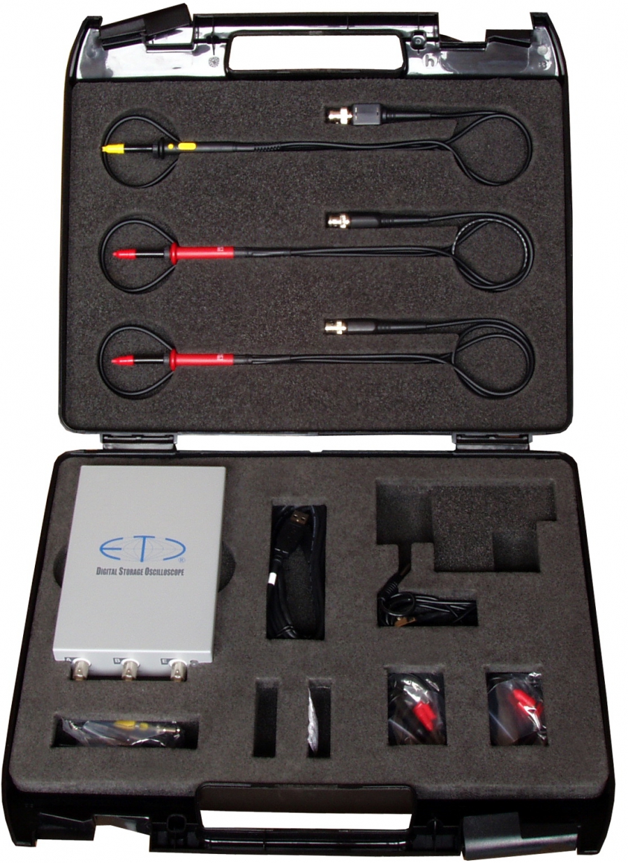
Price list

Prices not listed here are available on request from our sales department.
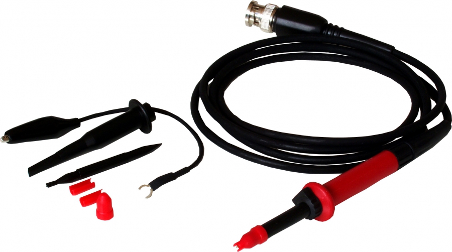
Product Catalogue number Price excl. VAT Price incl. VAT
Application specific kits
Kit for power system measurements
M774 oscilloscope with accessories for power system measurements in a tough carry case
KPWR n/a n/a
Kit for wide bandwidth measurements
M595 oscilloscope with accessories for wide bandwidth measurements in a tough carry case
KWBH n/a n/a
Universal oscilloscope kit
M774 oscilloscope with accessories for most measurements in a tough carry case
KUNI n/a n/a
Device specific kits
Oscilloscope kit based on the 60MHz M521 oscilloscope
M521 oscilloscope with accessories in a tough carry case
K521 n/a n/a
Oscilloscope kit based on the 60MHz M522 oscilloscope
M522 oscilloscope with accessories in a tough carry case
K522 n/a n/a
Oscilloscope kit based on the 120MHz M523 oscilloscope
M523 oscilloscope with accessories in a tough carry case
K523 n/a n/a
Oscilloscope kit based on the 150MHz M526 oscilloscope
M526 oscilloscope with accessories in a tough carry case
K526 n/a n/a
Oscilloscope kit based on the 150MHz M574 oscilloscope
M574 oscilloscope with accessories in a tough carry case
K574 n/a n/a
Oscilloscope kit based on the 350MHz M595 oscilloscope
M595 oscilloscope with accessories in a tough carry case
K595 n/a n/a
Oscilloscope kit based on the 150MHz M774 oscilloscope
M774 oscilloscope with accessories in a tough carry case
K774 n/a n/a
Signal generation kit based on the M531 generator
M531 generator with accessories in a tough carry case
K531 n/a n/a
M770 series USB oscilloscopes
150 MHz two-channel isolated USB oscilloscope RM
complete package with software for W98SE, ME, 2000, XP and Vista + Roll mode
M774/RM n/a n/a
150 MHz two-channel isolated USB oscilloscope RM/PRO
complete package with software for W98SE, ME, 2000, XP and Vista + Roll mode + Development kit
M774/RM/PRO n/a n/a
M590 series USB oscilloscopes
350 MHz two-channel USB oscilloscope RM
complete package with software for W98SE, ME, 2000, XP and Vista + Roll mode
M595/RM n/a n/a
350 MHz two-channel USB oscilloscope RM/PRO
complete package with software for W98SE, ME, 2000, XP and Vista + Roll mode + Development kit
M595/RM/PRO n/a n/a
M570 series USB oscilloscopes
150 MHz two-channel USB oscilloscope RM
complete package with software for W98SE, ME, 2000, XP and Vista + Roll mode
M574/RM n/a n/a
150 MHz two-channel USB oscilloscope RM/PRO
complete package with software for W98SE, ME, 2000, XP and Vista + Roll mode + Development kit
M574/RM/PRO n/a n/a
M520 series USB oscilloscopes
60 MHz two-channel USB oscilloscope RM
complete package with software for W98SE, ME, 2000, XP and Vista + Roll mode
M521/RM n/a n/a
60 MHz two-channel USB oscilloscope RM/PRO
complete package with software for W98SE, ME, 2000, XP and Vista + Roll mode + Development kit
M521/RM/PRO n/a n/a
60 MHz two-channel USB oscilloscope RM
complete package with software for W98SE, ME, 2000, XP and Vista + Roll mode
M522/RM n/a n/a
60 MHz two-channel USB oscilloscope RM/PRO
complete package with software for W98SE, ME, 2000, XP and Vista + Roll mode + Development kit
M522/RM/PRO n/a n/a
120 MHz two-channel USB oscilloscope RM
complete package with software for W98SE, ME, 2000, XP and Vista + Roll mode
M523/RM n/a n/a
120 MHz two-channel USB oscilloscope RM/PRO
complete package with software for W98SE, ME, 2000, XP and Vista + Roll mode + Development kit
M523/RM/PRO n/a n/a
150 MHz two-channel USB oscilloscope RM
complete package with software for W98SE, ME, 2000, XP and Vista + Roll mode
M526/RM n/a n/a
150 MHz two-channel USB oscilloscope RM/PRO
complete package with software for W98SE, ME, 2000, XP and Vista + Roll mode + Development kit
M526/RM/PRO n/a n/a
Arbitrary waveform generators
Single-channel USB arbitrary waveform generator with 100MSps sampling rate
complete package with software for W98SE, ME, 2000, XP and Vista
M531 n/a n/a
Single-channel USB arbitrary waveform generator with 100MSps sampling rate, PRO version
complete package with software for W98SE, ME, 2000, XP and Vista + Development kit
M531/PRO n/a n/a
Logic analyzers
Logic analyzer, external
+4xEA111+4xEA327/8S - complete package with software for W98, ME, 2000 and XP
M611/E n/a n/a
Logic analyzer, external, PRO
+4xEA111+4xEA327/8S - complete package with software for W98, ME, 2000 and XP + development kit
M611/E/PRO n/a n/a
Auxiliary equipment
USB adapter for EML II EC602 n/a n/a
Adapter for connecting two devices to one cable EA604/2 n/a n/a
Adapter for connecting more devices EA604/4 n/a n/a
Control panel for USB oscilloscopes EA500-0 n/a n/a
Accessories
Probes
switchable 1:1:10/60MHz, 1.2m E261/06 22 EUR 27.1 EUR
1:10/350MHz, 1.0m E251/35 n/a n/a
1:100/60MHz, 1.2m E252/06 50 EUR 61.5 EUR
1:100/150MHz, 1.2m E252/15 n/a n/a
1:100/250MHz, 1.3m E252/25 65 EUR 80 EUR
1:1000/10MHz, 1.3m E253/01 198 EUR 243.5 EUR
Ignition probe E273 n/a n/a
Differential probe 1:1:10, 10/50 MHz EA132 n/a n/a
Terminators and attenuators
Set of attenuators E324/4 45 EUR 55.4 EUR
Test leads and kits
SMD tweezers - banana plugs E133 n/a n/a
Test lead kit E134/S n/a n/a
Test lead kit E135/S n/a n/a
BNC-BNC 50ohm, black, 1m E350/01 n/a n/a
BNC-BNC 75ohm, black, 1m E370/01 n/a n/a
BNC adapters
Adapter BNC-banana plugs E390/BN 10 EUR 12.3 EUR
Accessories for M611
Logic probe, 8 channels, TTL, CMOS 5V, CMOS 3.3V EA111 n/a n/a
Logic probe, 8 channels, ±15V, threshold ±5V EA112 n/a n/a
Set of clips EA327/8S n/a n/a
Clip adapter for SMD EA328 n/a n/a
Clip for SMD circuits KL611 n/a n/a
Accessories for M631
Digital adapter set for M631/E A631/E n/a n/a
Optional software
M520 development kit - single device licence ES520DK/S n/a n/a
M520 development kit - multi-licence ES520DK/M n/a n/a
M520 roll mode - single device licence ES520RM n/a n/a
M570 development kit - single device licence ES570DK/S n/a n/a
M570 development kit - multi-licence ES570DK/M n/a n/a
M570 roll mode - single device licence ES570RM n/a n/a
M590 development kit - single device licence ES590DK/S n/a n/a
M590 development kit - multi-licence ES590DK/M n/a n/a
M590 roll mode - single device licence ES590RM n/a n/a
M770 development kit - single device licence ES770DK/S n/a n/a
M770 development kit - multi-licence ES770DK/M n/a n/a
M770 roll mode - single device licence ES770RM n/a n/a
M530 development kit - single device licence ES530DK/S n/a n/a
M530 development kit - multi-licence ES530DK/M n/a n/a
M631 development kit - single device licence ES631DK/S n/a n/a
M631 development kit - multi-licence ES631DK/M n/a n/a
M611 development kit - single device licence ES611DK/S n/a n/a
M611 development kit - multi-licence ES611DK/M n/a n/a

All prices are in EUR, EXW Žilina

How to buy

ETC s.r.o. supplies its products to customers in the Slovak Republic directly. We offer several ways of purchasing; whichever you choose, we trust you will be satisfied with our products and services. If you have any questions, please contact our Sales Department.

Ordering

Please send your order by e-mail or fax:

E-mail: Sales Department

Fax: +421 41 5652687

Shipping

Orders are shipped by the DPD courier service. The shipping cost is not included in the product price.

Payment

Payment can be made in two ways:

  • Bank transfer
  • Cash on delivery

Complaints

Complaints can be made to the seller or directly to ETC s.r.o.

ETC s.r.o.

Rosinská cesta 8

010 08 Žilina

Phone: 041 5652687

More information about complaints can be found in the Complaints procedure.

Personal data protection

Information that the controller shall be obliged to provide a data subject with

under Article 13 et seq. of Regulation (EU) 2016/679 of the European Parliament and the Council on the Protection of Natural Persons with regard to the Processing of Personal Data and on the Free Movement of Such Data

(hereinafter referred to as “the Regulation “)

intended for customers of the controller as well as for other data subjects.

1. The controller and their contact details:

Business Name: ETC s.r.o.

(i.e. limited liability company)

Registered Place of Business: Rosinská cesta 8, 010 08 Žilina

Company Identification (Registration) Number: 31641393

2. Purpose of processing personal data, legal basis of processing and categories of personal data concerned:

The controller shall process personal data of their customers in the extent required for conclusion of contractual relation in selling merchandise and services of the controller. The controller shall process those personal data without consent of the customers for the purpose of performance of their obligations resulting from a purchase contract and for the purpose of other communication with the customer concerned. Should no personal data be provided to the controller, the controller cannot properly perform a contract as concluded with the purchaser and therefore it will not be possible to conclude such contract with the purchaser. The personal data shall also be processed for the purpose of accountancy and business office work. At the same time processing of the same on the part of the controller results in fulfilment of their legal obligation following from special legal regulations, such as the Act on Accountancy, Act on Value Added Tax etc., and processing of the same is therefore necessary. The controller shall for those purposes process regular categories of personal data, in particular academic degree, name and surname, signature, permanent address, address for service, account number, telephone number, e-mail address and other necessary personal data.

The controller shall also process personal data of their customers for marketing purposes to support sales of their products, for example in the form of a newsletter, information e-mail messages and offers sent etc. in the extent as follows: name, surname and e-mail address. Legal basis to send such offers shall be legitimate interest of the controller which shall be provision of relevant information that may benefit the customers. Should a customer decide that they do not want to receive such marketing offers anymore, they may cancel them by clicking a cancellation link, a direct part of e-mail communication. The controller may also process personal data of data subjects other than their customers obtained for example from web forms etc. in the extent as follows: user name and e-mail address. The controller shall for marketing purposes and for the purposes of sending e-mail offers only process those personal data with consent of the data subject concerned. The data subject concerned may cancel their consent to receiving e-mail offers by clicking a cancellation link, a direct part of e-mail communication.

3. The recipients of personal data:

The controller shall provide personal data to processors that shall be mandated on the part of the controller in writing to process personal data, for example for the purpose of delivery, repairs, warranty and post warranty serviceof products, to providers of information systems and cloud platforms etc. The controller may for the purpose of exercise of their legal claim also provide personal data to public authorities, companies recovering claims and to other parties. At the same time the controller declare that they do not provide any personal data to subjects in third countries where personal data are not protected on appropriate level.

4. Storage period of personal data:

The controller shall not process personal data of data subjects longer than necessary for the performance of obligations resulting from the contractual relation and after the purpose that the same is processed for is achieved. The controller shall also process personal data of data subjects within the meaning of relevant provisions of the Act on Archiving (Act no. 395/2002 Coll. on Archives and Registries as amended – accounting documents for 10 years, while orders for 3 years), the same shall then be disposed of. Personal data shall for marketing purposes be processed for five years from obtaining the same or from obtaining consent to processing the same. After achieving the purpose of processing and expiration of storage period of personal data the controller shall immediately arrange disposal of personal data of the data subject, this shall not apply, should the personal data form a part of a record of registry.

5. Rights of data subjects:

A data subject shall in connection with processing their personal data have the following rights towards the controller:

a) The right to obtain confirmation as to whether or not personal data concerning him or her are  being processed, and, where that is the case, access to the personal data and the information hereunder;

b) The right to obtain from the controller without undue delay the rectification of inaccurate personal data concerning him or her and the right to have incomplete personal data completed;

c) The right to erasure (right to be forgotten) of his or her personal data if the same are not necessary for the purposes that it was collected or otherwise processed for and period of storage thereof already expired;

d)The right to obtain from the controller restriction of processing where one of the following applies:

- the accuracy of the personal data is contested by the data subject, for a period enabling the controller to verify the accuracy of the personal data;

- the processing is unlawful and the data subject opposes the erasure of the personal data and requests the restriction of their use instead;

- the controller no longer needs the personal data for the purposes of the processing, but they are required by the data subject for the establishment, exercise or defence of legal claims;

e) The right to receive the personal data concerning him or her, which he or she has provided to a controller, as well as the right to transmit those data to another controller if the processing is carried out by automated means on the basis of a contract or consent and is technically possible;

f) The right to object processing of personal data concerning him or her on the part of the controller processed on the grounds of legitimate interests of the controller. Should the controller fail to prove existence of a serious legitimate interest to process personal data that overrides rights and freedoms of the data subject, the controller shall terminate processing such personal data without undue delay;

g) The right to lodge a complaint with the Personal Data Protection Office if he or she believes that processing of personal data concerning him or her on the part of the controller is in conflict with legal regulations on protection of personal data;

h) The right to object to and not to submit himself or herself to a decision of the Office that would result in legal effects affecting him or her or in significant impact on him or her if such decision is issued solely on the basis of automated processing of personal data. The controller declares that they do not perform automated decision-making affecting in legal terms the data subjects without human judgment;

i) If personal data were not collected from the data subject, such data subject shall be entitled to be informed of the source that his or her personal data were collected from, or as the case may be, be informed as to whether the personal data are from open sources.

Downloads

Software, drivers, development kits and documentation for ETC products – 341 files in total. The latest versions are always available free of charge.

M52074
Software46
Basic software16
v4.002
v3.022
v3.012
v3.002
v2.032
v2.022
v2.012
v2.002
Roll mode12
Spectrum analyzer4
Development Kit14
Documentation28
Basic guide16
Roll mode8
Spectrum analyzer4
M53014
M57054
Software30
Basic software16
v4.002
v3.022
v3.012
v3.002
v2.032
v2.022
v2.012
v2.002
Roll mode6
Spectrum analyzer4
Development kit4
Documentation24
Basic guide16
Roll mode4
Spectrum analyzer4
M59048
Software26
Basic software16
v4.002
v3.022
v3.012
v3.002
v2.032
v2.022
v2.012
v2.002
Roll mode2
Spectrum analyzer4
Development kit4
Documentation22
Basic guide16
Roll mode2
Spectrum analyzer4
M61126
Software20

For Win2000/XP, install the EtcEpb driver if the device is connected to LPT, or the EtcUsb driver if it is connected to USB (via the EC602 adapter). Vista/7 support only the USB connection and require the EtcUsb driver.

Basic software13

Version changelog

For Win2000/XP, install the EtcEpb driver if the device is connected to LPT, or the EtcUsb driver if it is connected to USB (via the EC602 adapter). Vista/7 support only the USB connection and require the EtcUsb driver.

For Win 2000/XP/Vista/7/87

For Win2000/XP, install the EtcEpb driver if the device is connected to LPT, or the EtcUsb driver if it is connected to USB (via the EC602 adapter). Vista/7 support only the USB connection and require the EtcUsb driver.

v1.061

For Win2000, install the etcepb driver if the device is connected to LPT, or the etcusb driver if it is connected to USB (via the EC602 adapter). XP/Vista/7/8 support only the USB connection and require the etcusb driver.

v1.052
v1.042
v1.032
For Win98/ME6

For Win98/ME, install the etcepb driver if the device is connected to LPT, or the etcusb driver if it is connected to USB (via the EC602 adapter).

v1.052

For Win98/ME, install the etcepb driver if the device is connected to LPT, or the etcusb driver if it is connected to USB (via the EC602 adapter).

v1.042

For Win98/ME, install the etcepb driver if the device is connected to LPT, or the etcusb driver if it is connected to USB (via the EC602 adapter).

v1.032

For Win98/ME, install the etcepb driver if the device is connected to LPT, or the etcusb driver if it is connected to USB (via the EC602 adapter).

Drivers5
Development kit2
Documentation6
M62110
Software8

For Win2000/XP, install the EtcEpb driver if the device is connected to LPT, or the EtcUsb driver if it is connected to USB (via the EC602 adapter). Vista/7 support only the USB connection and require the EtcUsb driver.

Version changelog

Basic software4

For Win2000/XP, install the EtcEpb driver if the device is connected to LPT, or the EtcUsb driver if it is connected to USB (via the EC602 adapter). Vista/7 support only the USB connection and require the EtcUsb driver.

For Win2000/XP/Vista/72
For Win98/ME2
Drivers2
Development kit2
Documentation2
M63116
Software14

For Win2000/XP, install the EtcEpb driver if the device is connected to LPT, or the EtcUsb driver if it is connected to USB (via the EC602 adapter). Vista/7 support only the USB connection and require the EtcUsb driver.

Basic software10
Drivers2

For Win2000/XP, install the EtcEpb driver if the device is connected to LPT, or the EtcUsb driver if it is connected to USB (via the EC602 adapter). Vista/7 support only the USB connection and require the EtcUsb driver.

EtcEpb1
EtcUsb1
Development kit2
Drivers0
Documentation2
M77048
Software26
Basic software16
v4.002
v3.022
v3.012
v3.002
v2.032
v2.022
v2.012
v2.002
Roll mode4
Spectrum analyzer4
Development kit2
Documentation22
Basic guide16
Roll mode2
Spectrum analyzer4
M22117
M32115
M12219
EA500-04
EA1212
EA1321
EA1331
Educational programs2

Frequently asked questions

USB oscilloscopes

M520 series

Where can I find software compatible with Linux?

Unfortunately, software compatible with Linux is not available.

I need to measure the phase difference of two signals, one displayed on channel A and the other on channel B. Does the software support this?

Yes, with the Phase Finder (PF) function, which is part of the standard software package.

I would like to make sure that the M525 and M526 USB oscilloscopes can handle 200 MS/s on each channel (do they have two A/D converters with a sampling rate of 200 MS/s)?

Yes, the M525/526 oscilloscopes have two converters with a sampling rate of 200 MS/s.

Isolated USB oscilloscopes

Where can I find software compatible with Linux?

Unfortunately, software compatible with Linux is not available.

I need to measure the phase difference of two signals, one displayed on channel A and the other on channel B. Does the software support this?

Yes, with the Phase Finder (PF) function, which is part of the standard software package.

Oscilloscopes with long waveform memory

Where can I find software compatible with Linux?

Unfortunately, software compatible with Linux is not available.

I need to measure the phase difference of two signals, one displayed on channel A and the other on channel B. Does the software support this?

Yes, with the Phase Finder (PF) function, which is part of the standard software package.

Arbitrary waveform generators

M631

I own an M631 generator and would like to connect it to my computer via USB. Can I use a standard USB-LPT adapter?

The only verified way to connect the M631 to USB is the ETC EC602 adapter. We are not aware of any other working solution.

Logic analyzers

M611

Is it possible to measure with different types of probes at the same time?

Yes. Up to four probes (8 channels each) can be connected to the M611 analyzer. Each of them can be of a different type; the software recognizes the probe type and offers the corresponding settings.

If I use all 32 bits, how many samples can be recorded?

The internal memory of the analyzer is 2 MB = 524,280 32-bit words, so 524,280 samples can be recorded.

What is the difference between timing and state analysis?

In timing analysis, data acquisition is clocked by the time base generator, an internal unit of the analyzer. In state analysis, data acquisition is clocked by an external signal (from the device under test), usually one of its control signals, so the analyzer records the state of the signals relative to this control signal, without information about the time at which they occurred.

I own an M611 analyzer and would like to connect it to my computer via USB. Can I use a standard USB-LPT adapter?

The only verified way to connect EML II devices via USB is the ETC EC602 adapter. We are not aware of any other working solution.

M621 oscilloscope

M621

If I connect the device to the computer through the USB adapter (EC602), will the communication be slower?

No. Using the EC602 adapter actually speeds up communication by about 25%.

I have an M621 oscilloscope with a parallel port interface and would like to connect it via USB. Is a USB to Bitronics (25-pin parallel port) adapter enough for error-free communication?

The communication protocol of the M621 oscilloscope is more complex than communication with a printer. The only verified way to connect the M621 to USB is the ETC EC602 adapter. No other solutions are known so far.

Dealers

ETC s.r.o. products are exported worldwide. Please contact the dealer for your region; where there is none, you can order directly from us.

Dataman USA and Canada

General Information

215 Michigan Avenue
Orange City, FL 32763
USA

Phone
386-774-7785
Fax
386-774-7796
E-mail
ussales@dataman.com
Web
www.dataman.com

Dataman uses different names for ETC products. Please refer to the cross-reference table.

Technical Support

215 Michigan Avenue
Orange City, FL 32763
USA
USA

Phone
386-774-7785
Fax
386-774-7796
E-mail
support@dataman.com
Web
www.dataman.com

Dataman uses different names for ETC products. Please refer to the cross-reference table.

Sales

215 Michigan Avenue
Orange City, FL 32763
USA
USA

Phone
800-328-2336
Fax
386-774-7796
E-mail
ussales@dataman.com
Web
www.dataman.com

Dataman uses different names for ETC products. Please refer to the cross-reference table.

Dataman UK and Ireland

Sales

Unit 2 Newton Hall
Dorchester Road
Maiden Newton
Dorset
DT2 0BD
United Kingdom

Phone
+44 (0) 1300 320719
Fax
+44 (0) 1300 321012
E-mail
sales@dataman.com

Dataman uses different names for ETC products. Please refer to the cross-reference table.

General Information

Unit 2 Newton Hall
Dorchester Road
Maiden Newton
Dorset
DT2 0BD
United Kingdom

Phone
+44 (0) 1300 320719
Fax
+44 (0) 1300 321012
E-mail
info@dataman.com

Dataman uses different names for ETC products. Please refer to the cross-reference table.

Technical Support

Unit 2 Newton Hall
Dorchester Road
Maiden Newton
Dorset
DT2 0BD
United Kingdom

Phone
+44 (0) 1300 322903
Fax
+44 (0) 1300 321012
E-mail
support@dataman.com

Dataman uses different names for ETC products. Please refer to the cross-reference table.

Contact

Company details

ETC s.r.o.
Rosinská cesta 8
010 08 Žilina
Slovak Republic

Company ID
31641393
Fax
+421 41 5652687

Page not found

The requested page does not exist. Continue to the home page or the product overview.